
How to make an automatic plant watering system
INTRODUCTION: –
Today we are making something that is not only interesting but also very useful in our day-to-day busy schedule of us. So today we are going to describe How to make an automatic plant watering system, out of Arduino and a few other small sensors and other stuff, and have a look at how it works. It is very useful in Northern areas because due to less sunlight and high humidity it is very hard to grow plants.
Plants need special care and time to time water and nutrition for better and healthy growth but in this busy world, we find it hard to do it so here we will try to make it easy to observe and operate. It can be used anywhere on the farm or on a small piece of land to monitor the correct water requirement for plants. There are also IoT projects on the same topic.
What is automatic plant watering?
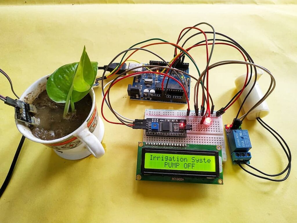
As the name of projects How to make auto watering system suggests we are going to use a Soil Moisture sensor along with Arduino Uno and a small pump to demonstrate the working of this project and to show its applications in real life. We’ll also use a small dc pump, I2C 16×2 LCD and an RGB led to display the status of every task.
The sensor also has an onboard power led and also an onboard Status led which will turn on if any moisture is detected.
The sensor gives an analog output that varies according to the moisture in the soil, it can also be adjusted by the provided potentiometer on board. there is another Smart irrigation project for a major project
*NOTE: – THIS SENSOR IS VULNERABLE RUSTING IN THE SOIL SO FOR PERMANENT OR LONG TIME USE BETTER QUALITY SENSOR AVAILABLE IN THE MARKET.
FEATURES AND APPLICATIONS: –
- The sensitivity of moisture in the soil is good
- Easy to use
- Adjustable value by pot
- Low price
- Can be used in small projects and irrigation demonstration.
SENSOR SPECIFICATIONS: –
COMPONENTS NEEDED FOR AUTOMATIC WATERING PLANT: –
- Arduino UNO-BUY LINK
- LED-BUY LINK
- A moisture sensor-BUY LINK
- A breadboard-BUY LINK
- Jumper wires-BUY LINK
- 220ohm Resistor-BUY LINK
- Relay module-BUY LINK
- DC pump-BUY LINK
- 16×2 LCD-BUY LINK
- Power supply-BUY LINK
You Can Buy All Components To Together-BUY LINK
SMART IRRIGATION CIRCUIT DIAGRAM:

| Arduino UNO | Soil Moisture Sensor | |
| D3 Pin | DO OUT Pin | |
| ( +5V ) VCC | VCC , ( + 5V ) | |
| GND ( Ground ) | GND | |
| Arduino UNO | I2C LCD Module | |
| A4 Pin ( SDA Pin ) | SDA Pin | |
| A5 Pin ( SCL Pin ) | SCL Pin | |
| ( +5V ) VCC | VCC | |
| GND ( Ground ) | GND | |
| 16 * 2 LCD | I2C LCD Module | |
| 16 Connect | 16 Connect | |
| Arduino UNO | Single Channel Relay Module | |
| D4 Pin | IN1 | |
| +5 VCC | VCC | |
| G, GND | GND | |
| DC Water Pump | DC Supply | Relay Module |
| Normally Open | ||
| Positive | Common | |
| Terminal 1 | Normally Closed | |
| Terminal 2 | Negative | |
| Arduino UNO | RGB Led | 220 Ohm Resistor |
| D5 Pin | Terminal 1 | |
| Terminal 2 | Terminal 1 | |
| D6 Pin | Terminal 3 | |
| D8 Pin | Not connect | |
| GND | Terminal 2 |
First, take the power lines onto the breadboard from the microcontroller
VCC/5v–>+ line and GND–> – line.
Then connect the sensor to the breadboard and connect power to the sensor from powerlines using jumper wires.
Now connect OUT PIN OF SENSOR TO MICROCONTROLLER DIGITAL PIN 3.
Now connect led to the breadboard – to gnd in series with resistor and + wire of different color to Arduino pins as shown in the figure.
Also connect I2C LCD, Relay, and Pump according to the diagram above.
how include library click here
CODE: –
 //put this code in the ide of arduino from this line
 #include <Wire.h>
 #include <LiquidCrystal_I2C.h>
 LiquidCrystal_I2C lcd(0x27,16,2);
 int val = 0 ;
 void setup()
 {
 Serial.begin(9600);
 lcd.init();
 lcd.backlight();
 pinMode(3,INPUT); // pir sensor output pin connected
 pinMode(4,OUTPUT);
 pinMode(5,OUTPUT);
 pinMode(6,OUTPUT);
 digitalWrite(4,HIGH);
 lcd.setCursor(0,0);
 lcd.print("Irrigation System ");
 }
 void loop()
 {
 val = digitalRead(3); // soil moisture sensor output pin connected
 Serial.println(val); // see the value in serial mpnitor in Arduino IDE
 delay(1000);
 if(val == 1 )
 {
 digitalWrite(4,LOW);
 digitalWrite(5,LOW);
 digitalWrite(6,HIGH);
 lcd.setCursor(0,1);
 lcd.print(" PUMP ON ");
 }
 else
 {
 digitalWrite(4,HIGH);
 digitalWrite(5,HIGH);
 digitalWrite(6,LOW);
 lcd.setCursor(0,1);
 lcd.print(" PUMP OFF ");
 }
 }
If you are new to the Arduino and don’t have any idea about u[load the code into the Arduino you can see here how to upload code in Arduino
WORKING: –
Code starts with initializing the library used in the project and then sets the I2C LCD address and starts it. In void setup, it set the pin modes as INPUT or OUTPUT. And start displaying on LCD.
In a loop, it then reads the value from the soil moisture sensor and according to the condition changes the color of the led and also tuns on or off the pump along with displaying on LCD.
Smart Irrigation System using Arduino
Smart Irrigation system Raspberry Pi
Soil moisture sensor with Arduino interface