
Hey Hobbyist, I’m here with another important Basic Electronic article. Today we’re going to discuss 555 Timer IC or NE555. It is very common and mostly used IC in various circuits and schematics. As its wide range of usability and compatibility so, if you are using this ic you should know the 555 timer ic , Also it’s more range of operating voltage and various other features makes it ideal for wider use. So let’s jump onto our topic.
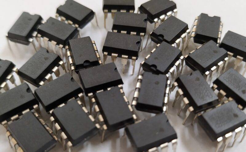
Table of Contents
What is NE555 IC:
NE555 is an 8pin IC that is used mostly. It has a large range of operating voltages ranging from +5V to +18V. It can behave as signal generator, oscillator, time-delay, flip-flop, etc.
Furthermore, it comes in many types of packages like PDIP-8, VSSOP-8, SOIC-8. But how small it may seem to be you’ll not believe that it comprises just two comparators, a D-type flip-flop, and an inverter.
You can also demonstrate this circuit on a PCB, but to reduce the time and space. Here is a glimpse of its internal schematic with pinout and components.
You can visit the official site of Texas Instruments for 555 timer ic datasheet for more information through PDF. As in the above image you can see it is clearly visible that it encloses two comparators with a voltage divider through Vcc Pin.
Also, it contains a D-type Flip-Flop and an inverter connected to the output pin of the IC. The pinout and more detailed internal Schematic can be seen inside the PDF through the given link above.
IC 555 Pin Diagram:-

555 Timer pin Description
Vcc: (PIN 8)
This is the Input voltage pin, which is connected to the voltage divider internally. Which is responsible for comparator functions and outputs.
GND: (PIN 1)
This is the ground pin, which is connected to 0(zero)V or the negative terminal of the battery.
TRIG (TRIGGER): (PIN 2)
This pin is connected to +(positive input) of the comparator, which determines the output of the 2nd comparator. The other input, i.e., – (negative input) of the comparator is connected to Vcc through a voltage divider at 1/3 Vcc voltage.
For example and easiness, If I take 9V at Vcc the at + there will be 3V, so TRIG pin should be below 3V in order to deliver high output from the comparator.
DISCH (DISCHARGE): (PIN 7)
This pin gives the 0V output or negative voltage, the same as connected to 555 IC. If you see it in the internal schematic, It is connected to the collector of the transistor.
Whose base is connected to the Q(bar) of the flip-flop? If you have guessed that it is an NPN transistor so whenever the output of the flip-flop goes high the output of the DISCH pin draws down to 0V.
OUT (OUTPUT): (PIN 3)
This is the output pin of the 555 Timer IC, which in all modes gives the output & in all circuits. This pin is internally connected to the flip-flop via an inverter between them, which reverses the output coming from the flip-flop.
In the PDF link provided if you see the IC’s internal circuit built out of transistors and resistors, you’ll notice that the output of the filp-flop is connected to two transistor bases, i.e., NPN & PNP.
Both these work simultaneously to give reverse output as compared to the flip-flop on the output pin.
THR (THRESHOLD): (PIN6)
If you look at the internal circuit above,
you’ll see that this pin is connected to the +(positive) input of a comparator, which is responsible for driving the output of the flip-flop.
The other pin of the comparator, i.e., – (negative) connected to the voltage divider at 2/3Vcc value. But it is not only responsible for determining output, but also the Control pin.
The output of the comparator is connected to the reset pin of the flip-flop, so when the output is high the flip-flop reset, and it gives low the output of the flip-flop but if it is low then the output of the flip-flop is decided by the signal at Q of the flip-flop.
RST (RESET): (PIN 4)
This pin is connected to the Master Reset of the flip-flop. Which reset the flip-flop regardless of the output of comparator 2. The small circle connected to this pin at the outline of the flip-flop determines the master reset of the flip-flop.
CTRL (CONTROL): (PIN 5)
This pin is connected to the – (negative) input of comparator 2 which is also connected to the 2/3Vcc voltage. You can view this pin either as input or output to view the output at the – of the 2nd comparator.
Or you can give input to this pin in order to change the output of the second comparator to determine the reset state of the flip-flops.
So with this brief introduction to the NE555 Timer IC. I hope you understand. If you want more information about its modes and demo circuit, then I’ll discuss them with you in some basic concepts projects with you. Until then, keep enjoying such stuff. if you know the basics of this ic you can see our 555 timer projects.

555 Timer IC Working
There are 8 pins on the 555 timer ic. as you can see in the above diagram. the 555 timer ic has many functions. but basically, it is used to generate the pulse. and you can adjust the width and time by the resistor and the capacitor used in the circuit. Such as you can see the different work in different projects like traffic light control using 555 timers.
Latest 555 timer project
555 delay timer with ON/OFF | Basic project with 555 timer
Electronic Mosquito Killer Using 555 Timer IC
LED Fade In And Out Circuit Using 555 Timer IC | electronic tutorial