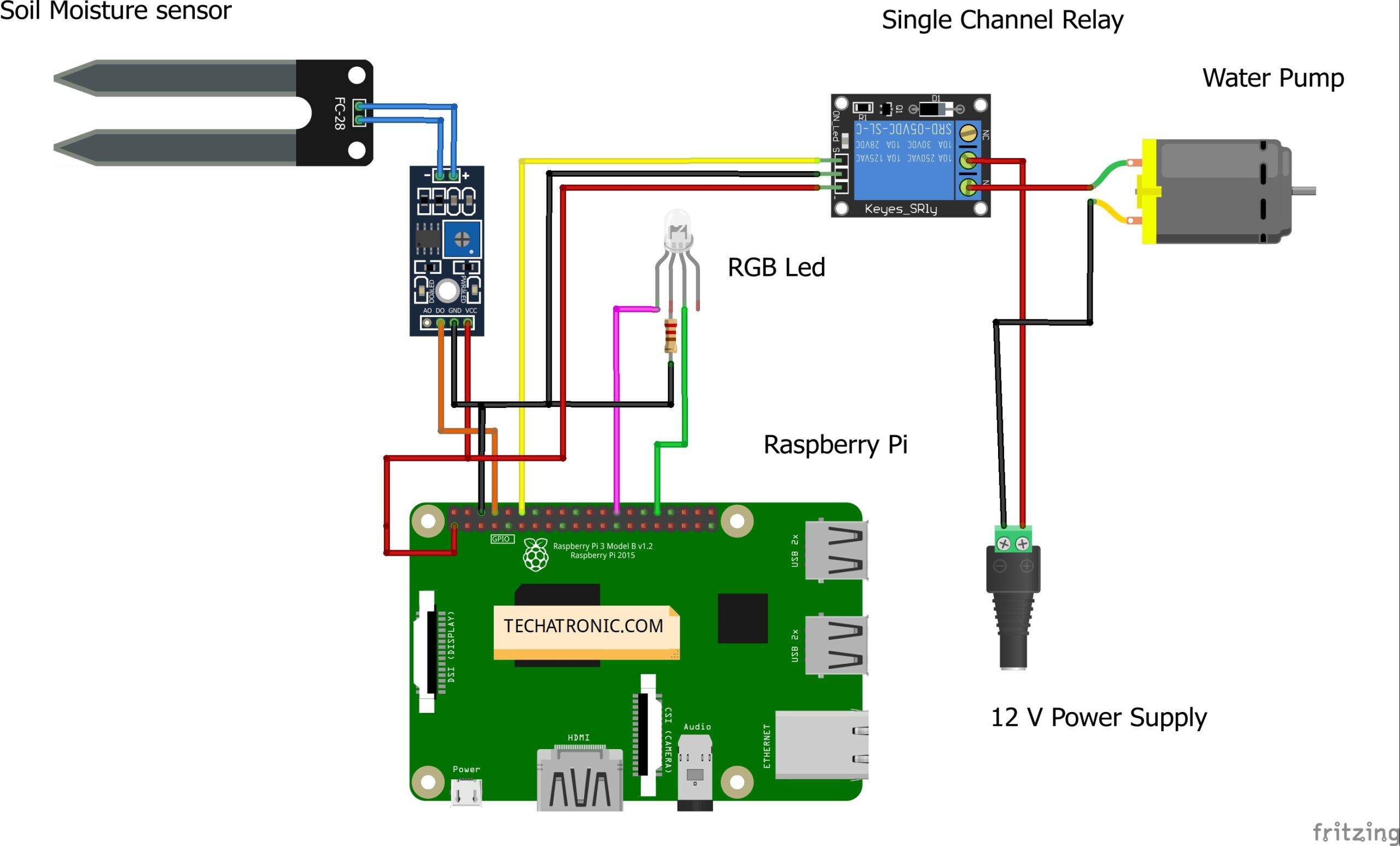
Welcome back, friends. Today I’m back again with a complete project based on Raspberry Pi which is a further extension of one of my previous articles. Recently I published a tutorial on Raspberry Pi soil moisture sensors. I hope you have viewed it carefully. Then to make that in a further extension I decided to build a smart irrigation system raspberry pi. So today we’ll do complete automation of smart irrigation using Pi.
Soil moisture sensor working:
I have explained it very clearly in my previous tutorial on the same topic. You may visit that for a more clear explanation. In brief, the soil moisture sensor is built out of LM393 IC which is an Op-Amp. it actually amplifies the voltage signal received when probes of the sensor dug into the ground. The amount of sensitivity of moisture in soil detected by probes directly varies the voltage signal.
Although the signal is detected it is not identified by Arduino alone it values change. So to make these changes effective we use an Op-Amp. The potentiometer on the sensor allows to change the sensitivity to some amount.
Material Required:
- Raspberry Pi with screen keyboard and mouse
- Soil-Moisture sensor
- RGB led with resistor
- Relay Module
- water pump
- Power Supply
Circuit Diagram:

|
Raspberry PI |
Soil Moisture Sensor | |
|
GPIO 14 Pin |
D0 | |
|
+5V | +5 V, VCC | |
|
GND |
GND | |
|
Raspberry PI |
5 Volt Relay Module | |
|
GPIO 18 |
IN Pin | |
|
+5 Volt |
VCC | |
|
GND |
GND | |
|
Raspberry PI |
RGB LED |
220 ohm Resistor |
|
GPIO 12 Pin |
Anode Terminal 1 |
|
|
GPIO 8 Pin |
Anode Terminal 3 |
|
|
GND |
|
Terminal 1 |
|
|
Cathode Terminal 2 |
Terminal 2 |
|
Power Pump |
5 Volt Relay Module |
Power Supply |
|
| Normally Open |
|
|
|
Common |
Positive |
|
Terminal 1 | Normally Close |
|
|
Terminal 2 |
|
Negative |
Programming:
For programming open Thonny Python IDE or create a new file using terminal ( sudo nano smart_irrigation.py).
First we import Raspberry Pi GPIO library as gp using first command i.e., ‘import RPi.GPIO as gp‘. Then we set numbering of pins according to BOARD pin numbers and also define some pins as input or output.
 gp.setmode(gp.BOARD)
 gp.setup(8,gp.IN)
 gp.setup(12,gp.OUT, initial=gp.LOW)
 gp.setup(26,gp.OUT,initial=gp.LOW)
 gp.setup(32,gp.OUT,initial=gp.LOW)
Now in while loop we put our main code which runs until a keybopard interrupt is encountered.
 while True:
   try:
     print(not gp.input(8))
     gp.output(36,gp.input(8))
     gp.output(32,not gp.input(8))
     gp.output(12,gp.input(8))
   except KeyboardInterrupt:
     gp.cleanup()
Here is the main complete code:
import RPi.GPIO as gp
 gp.setmode(gp.BOARD)
 gp.setup(8,gp.IN)
 gp.setup(12,gp.OUT, initial=gp.LOW)
 gp.setup(26,gp.OUT,initial=gp.LOW)
 gp.setup(32,gp.OUT,initial=gp.LOW)
 while True:
   try:
     print(not gp.input(8))
     gp.output(36,gp.input(8))
     gp.output(32,not gp.input(8))
     gp.output(12,gp.input(8))
   except KeyboardInterrupt:
     gp.cleanup()
Explanation:
As RPi has only digital pin, we can only detect 0 or 1 means HIGH or LOW signal from sensor. So when a High signal is encountered on Pi pin 8, it means there is no moisture in the soil. It is so because soil moisture sensor works on inverting output circuit op-amp. Using this circuit reverses the output on the digital data pin of soil moisture sensor.
So in order to turn on pump we put a not before all read statements in code and output to reverse the output as normally we want to get. then it turns on or off the pump and LED’s to show the current status of moisture in the soil.
With this we have completed our project of smart irrigation system raspberry pi. I hope you like it, and if you need my help then let me know.


The design is for single soil moisture sensor. How about multiple sensors?
Can a single Pi can handle multiple sensors situation and how the design will be? I’m new to this so I cannot figure out with my limited knowledge on it.
Thanks in advance
it is just simple. add more sensor with the more pins
I need this project for school . I already have everything except the LM393 IC. The code looks too short 😅. Does it really work ? like watering after a specific amount of time ?
And what are “Anode Terminal 1” , “Anode Terminal 3” and “Cathode Terminal 2” because My RGB-LED has only “R” ,”G”,”B” and “GND”. Sorry if this was a dumb question because I am a student and new to programming 😅.