
Table of Contents
Introduction
Hey guys, welcome back to Techatronic.
In today’s blog post we are going to describe how to make GSM-based home automation using Arduino as we all are familiar with the automation system.
which is widely used in offices and the home. In this era, the technology upgraded everywhere so we are making this project to aware that we can implement technology into our home and offices,
so if you are interested and you have a bit of knowledge in the electronics you can make it easy with the given instructions.
we have also made IOT Home automation in our previous article so if you want to make that project you can find it on our website.
to make this project work you need to read the full article carefully and the instructions too. Now, let’s start the project with the introduction. This is one of the best electronic projects for ece.
A preview image of Obstacle avoiding robot can be different from your own.
What is GSM based home automation system
As the name reflect the home automation system is related to the GSM. the automation system which runs on the GSM.
like Iot home automation system runs over the internet, Bluetooth home automation runs over Bluetooth. So it is very simple to understand what is GSM home automation system is.
A system that controls the electronics appliance over the GSM is known as the GSM-based home automation system.
To make this system you need to learn some basics of the gsm interface.
in this system, we control things by our phone messages and call. we can trigger the system by call and message.
for example, if we store” bulb off ” in the code with the trigger condition and we send the same in the message to the gsm “bulb off” then the connected bulb will turn off.
this is home automation using gsm and Arduino. same as we can control the Bulb, Fan, AC, and many more appliances.
How Does Arduino home automation work?
GSM, a global system for mobile communication as the name represents we also use it to control the home appliance.
- only we need to send a message or a call to trigger the circuit which controls the home appliances.
- when we send the message to the gsm attached with the Arduino,
- Arduino read the message by the serial communication and compare the message with the database message
- if the condition is true the instruction attached to the condition will start to run and if the condition is not true the Arduino checks another condition.
- this electronic project contains many components which are listed below. and it will check continuously till the condition will true,
- the same condition applies to the call. we need to insert a sim card inside the GSM module.
always preferred the sim900 module for SMS-based home automation. and 12v, 2amp power supply.
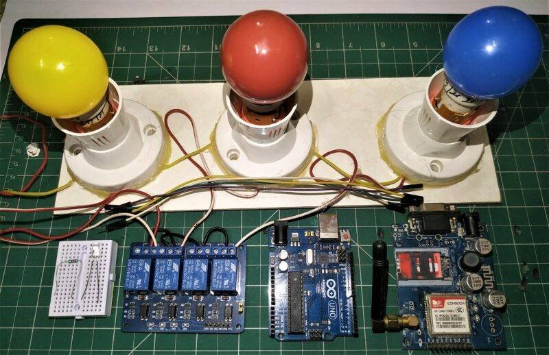
Component required:-
- Arduino Uno
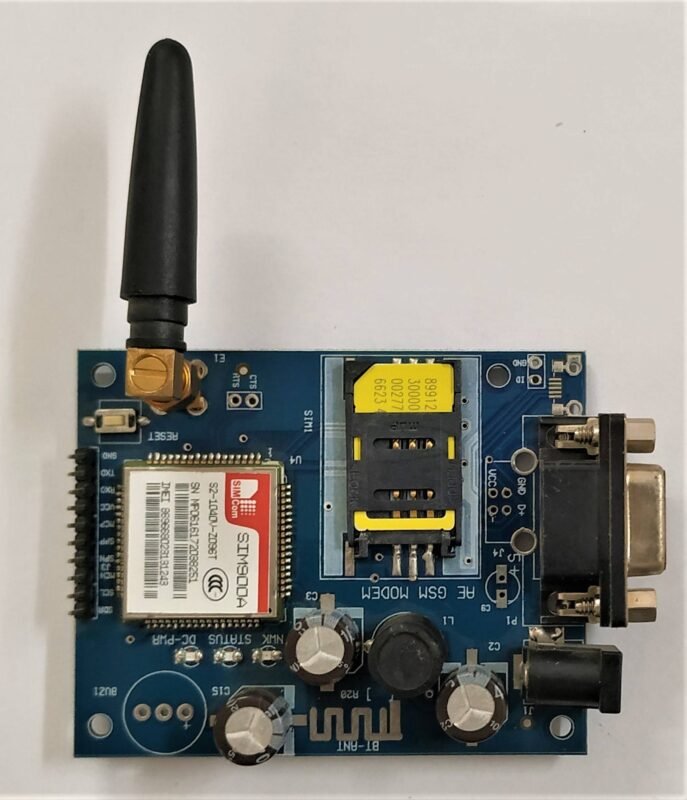
- SIM900
- 12V, 2amp power supply for gsm module
- 4 channel relay
- AC bulb
- AC bulb holder
- Socket
- 220ohm resistor
- Led
- Breadboard
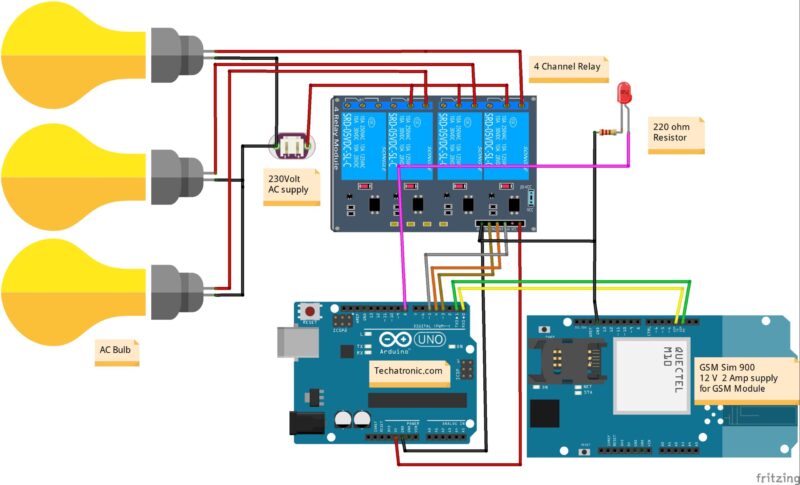
Gsm based Home automation Circuit Diagram:-
Fritzing-based diagrams help you make more clear connections still if you are stuck anywhere you can ask in the comment section.
Connection Table
| Arduino UNO | GSM SIM 900 Module | |
| RX PIN | TX PIN | |
| TX PIN | RX PIN | |
| GND | GND | |
| 12 Volt 2 Amp Adaptor | GSM SIM 900 Module | |
| Connect | Connect | |
| Arduino UNO | 4 Channel Relay Module | |
| 3 PIN | IN 1 | |
| 4 PIN | IN 2 | |
| 5 PIN | IN 3 | |
| 220 Volt AC supply | 4 Channel Relay Module | AC Bulb Holder |
| Neutral | Terminal 1 | |
| Phase | Common | |
| Normally Open | Terminal 2 | |
| Normally Closed | ||
| Arduino UNO | LED | Resistor |
| 9 PIN | Anode Terminal | |
| Cathode Terminal | Terminal 1 | |
| GND | Terminal 2 |
Important notes:-
- Connect Arduino ground to GSM ground
- Use always 12v , 2amp power supply for gsm
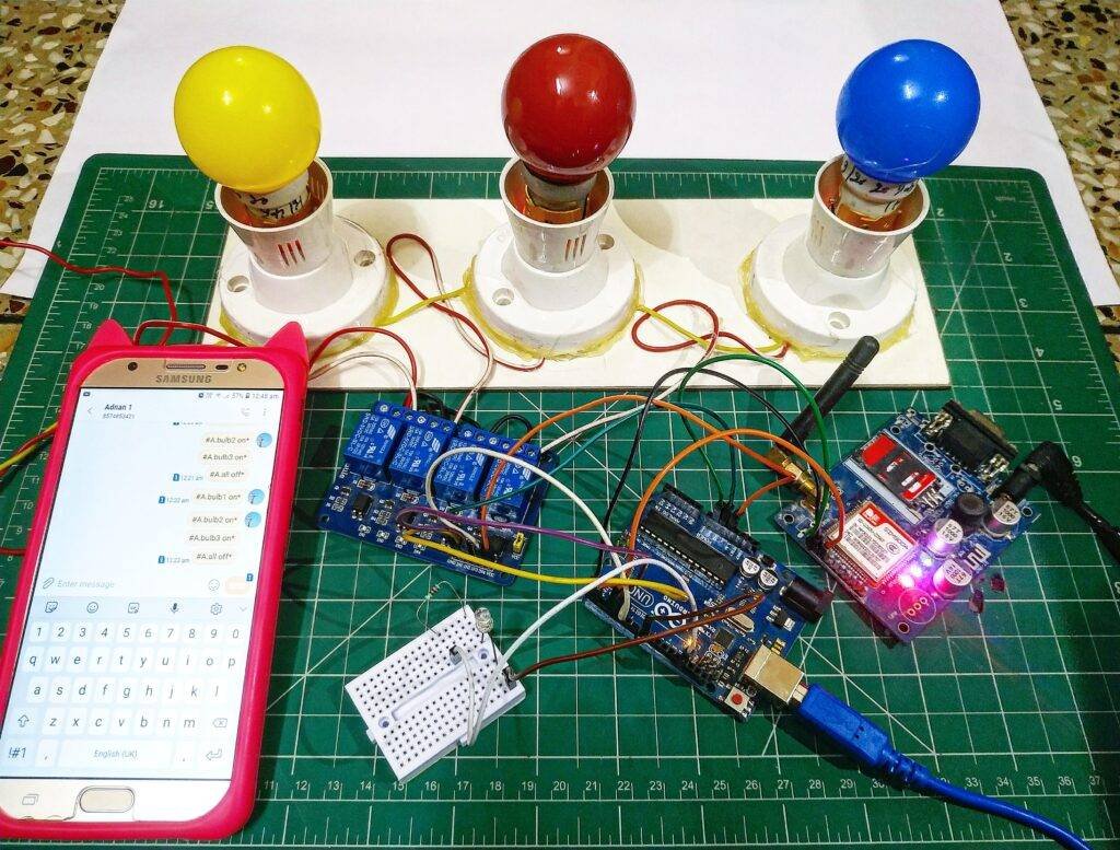
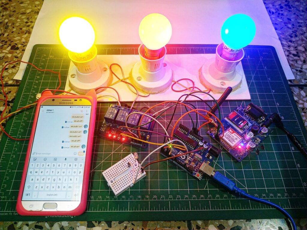
- To on bulb 1 send a message by your phone to gsm “#A.bulb1 on*“
- To off bulb 1 send a message by your phone to gsm “#A.bulb1 off*“
- To on bulb 2 send a message by your phone to gsm “#A.bulb2 on*“
- To on bulb 2 send a message by your phone to gsm “#A.bulb2 off*“
- To on bulb 3 send a message by your phone to gsm “#A.bulb3 on*“
- To on bulb 3 send a message by your phone to gsm “#A.bulb3 off*“
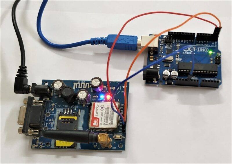
GSM Rx connect to Arduino Tx
GSM Tx connect to Arduino Rx
GSM gnd connect to Arduino gnd
Now we will look into the AT command of GSM Which controls all the instructions.
First, we need to send the AT to check the communication system is working or not. if all the things are right it will get return Ok. otherwise, it may be an error.
+CMGF command is used to set the msg mode in gsm sim900A.
+CMGW is used to store the msg
there is some command given below to use in sim900
Commands Use for Operation
|
Command
|
Description
|
|
AT+CSMS
|
To Select message service
|
|
AT+CPMS
|
To Preferred message storage
|
|
AT+CMGF
|
select Message format
|
|
AT+CSCA
|
Service center address
|
|
AT+CSMP
|
Set text mode parameters in sim
|
|
AT+CSDH
|
To Show text mode parameters in Sim
|
|
AT+CSCB
|
Select cell broadcast message types
|
|
AT+CSAS
|
Save settings in the gsm module
|
|
AT+CRES
|
Restore all settings
|
|
AT+CNMI
|
Message indications to TE
|
|
AT+CMGL
|
To make the list of messages
|
|
AT+CMGR
|
Read new message
|
|
AT+CMGS
|
Send a new message
|
|
AT+CMSS
|
Send message from sim storage
|
|
AT+CMGW
|
Write a message to gsm memory
|
|
AT+CMGD
|
Delete message
|
Gsm based Home automation Arduino Code:-
 // Techatronic.com
 #define Bulb1 3
 #define Bulb2 4
 #define Bulb3 5
 int temp=0,i=0;
 int led=8;
 char str[15];
 void setup()
 {
 Serial.begin(9600);
 pinMode(led, OUTPUT);
 pinMode(Bulb1, OUTPUT);
 pinMode(Bulb2, OUTPUT);
 pinMode(Bulb3, OUTPUT);
 digitalWrite(Bulb1,HIGH);
 digitalWrite(Bulb2,HIGH);
 digitalWrite(Bulb3,HIGH);
 Serial.println("AT+CNMI=2,2,0,0,0");
 delay(500);
 Serial.println("AT+CMGF=1");
 delay(1000);
 }
 void loop()
 {
 if(temp==1)
 {
 check();
 temp=0;
 i=0;
 delay(1000);
 }
 }
 void serialEvent()
 {
 while(Serial.available())
 {
 if(Serial.find("#A."))
 {
 digitalWrite(8, HIGH);
 delay(1000);
 digitalWrite(8, LOW);
 while (Serial.available())
 {
 char inChar=Serial.read();
 str[i++]=inChar;
 if(inChar=='*')
 {
 temp=1;
 return;
 }
 }
 }
 }
 }
 void check()
 {
 if(!(strncmp(str,"bulb1 on",8)))
 {
 digitalWrite(Bulb1, LOW);
 delay(200);
 }
 else if(!(strncmp(str,"bulb1 off",9)))
 {
 digitalWrite(Bulb1, HIGH);
 delay(200);
 }
 else if(!(strncmp(str,"bulb2 on",8)))
 {
 digitalWrite(Bulb2, LOW);
 delay(200);
 }
 else if(!(strncmp(str,"bulb2 off",9)))
 {
 digitalWrite(Bulb2, HIGH);
 delay(200);
 }
 else if(!(strncmp(str,"bulb3 on",8)))
 {
 digitalWrite(Bulb3, LOW);
 delay(200);
 }
 else if(!(strncmp(str,"bulb3 off",9)))
 {
 digitalWrite(Bulb3, HIGH);
 delay(200);
 }
 else if(!(strncmp(str,"all on",6)))
 {
 digitalWrite(Bulb1, LOW);
 digitalWrite(Bulb2, LOW);
 digitalWrite(Bulb3, LOW);
 delay(200);
 }
 else if(!(strncmp(str,"all off",7)))
 {
 digitalWrite(Bulb1, HIGH);
 digitalWrite(Bulb2, HIGH);
 digitalWrite(Bulb3, HIGH);
 delay(200);
 }
 }
Upload the given code into your Arduino with Arduino IDE software and if are new to Arduino and don’t know how to upload Arduino Code You can find the tutorial on our website. Thanks and all the best.
Video sample
