
Welcome to the Techatronic, in this article we will share with you How to make a metal Detector with the Arduino. Arduino is the basic controller board that is using widely in the area of basic-level projects. so this project I am making also on the same. A metal detector is an interesting and important project. which can be used in many placed like Metal waste segregator, and finding metal from the ground, and many other places.
I use the Metal Detector Using Arduino to find out the metal from my garden so that I will never hurt with that small pieces of metal. this metal detector is very easy and simple to make. you only need a small electronic circuit and have to embed this circuit with the Arduino board. So, let Talk about the working of the Arduino metal detector.

How does a metal detector work?
As we can see there are three things that are using to complete the whole project. Electronic circuit, Arduino, and a copper coil. here actually we are making a proximity sensor that detects the metal with a metal detector using Arduino. with the help of the RC circuit built in the Electronics part. now when we take this project near the metal it senses the metal near it due to the electromagnetic waves transmitted from the coil. hence with these electromagnetic waves,
the circuit sends a signal to the Arduino. Arduino compares and processes the data and sends the instruction to the buzzer and the LED according to the code. the coil will generate the electromagnetic waves and when we take it near to the metal the electromagnetic waves get distorted. and Arduino gives the instruction according to all these data variations. Here are more Arduino projects like Gesture Control Robot using Arduino to check it also.
There is in the metal detector we have a coil which is connected to the Arduino. so from the arduino we generate the square wave and pass to the coil. when the current introduce into to the coil then some electromagnetic field genrated into the coil and sense the metal near it.
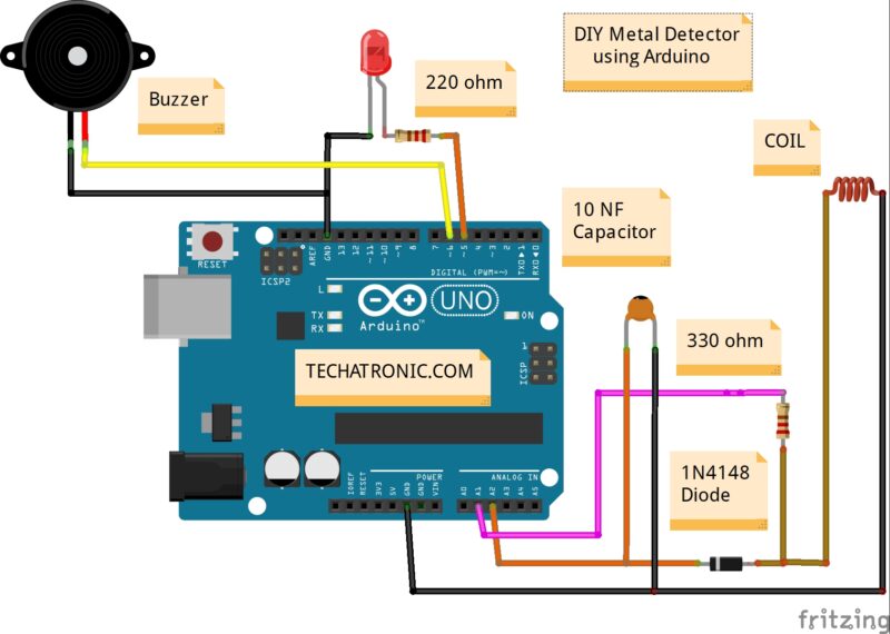
Arduino metal detector- DIY Metal Detector Using Arduino
At whatever point some present goes through the loop, it produces a magnetic field around it. Furthermore, the adjustment in the magnetic field produces an electric field. Presently as per Faraday’s law, due to this Electric field, a voltage creates over the curl which contradicts the adjustment in an attractive field and that is the way Coil builds up the Inductance, which implies the produced voltage restricts the expansion in the flow. Metal Detector Using Arduino easiest metal detector project The unit of Inductance is Henry and the equation to quantify the Inductance is:
L = (μο * N2 * A) / l
Where, L- Inductance in Henries
μο- Permeability,
its 4π*10-7 for Air
N- Number of turns
A- Inner Core Area (πr2) in m2 l-
Length of the Coil in meters
If you don’t have any idea about the Coils turn and thickness of the wire. so , here is the formula of the wire lenth and turn of coil.
Components Required
- Arduino UNO
- Copper coil
- Diode
- 10nf capacitor
- Buzzer
- Led
- 220 ohm & 330 Ohm Resistor
- Jumper wires and a breadboard
- USB cable for uploading the code
| S.No | Component Required | Quantity | Buy Link |
| 1. | Arduino UNO | 1 | Buy Link |
| 2. | Arduino UNO Cable | 1 | Buy Link |
| 3. | Copper Coil | 1 | Buy Link |
| 4. | Diode | 1 | Buy Link |
| 5. | LED | 2 | Buy Link |
| 6. | 220-ohm Resistor | 2 | Buy Link |
| 7. | 330-ohm Resistor | 1 | Buy Link |
| 8. | Buzzer | 1 | Buy Link |
| 9. | Breadboard | 1 | Buy Link |
| 10. | Power Supply | 1 | BUY LINK |
You Can Buy All Components To Together –BUY LINK
Circuit Diagram Metal Detector Using Arduino :-
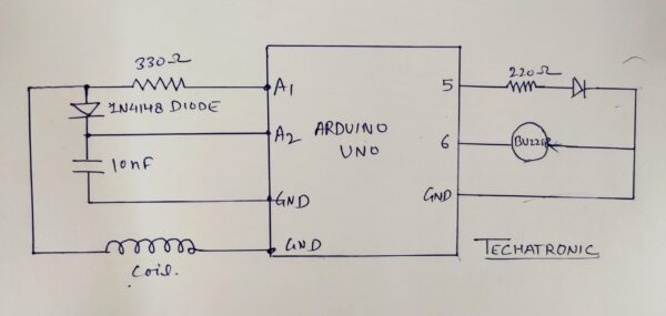
| Arduino UNO | 10 nf Capacitor | ||
| A2 Pin | Terminal 1 | ||
| GND | Terminal 2 | ||
| Arduino UNO | Buzzer | ||
| D6 Pin | Positive | ||
| GND | Negative | ||
| Arduino | LED | 220 Ohm Resistor | |
| D5 Pin | Terminal 1 | ||
| Anode Pin | Terminal 2 | ||
| GND | Cathode Pin | ||
| Arduino UNO | Copper coil | Diode | 330-ohm res |
| Terminal 1 | Terminal 1 | Terminal 1 | |
| A1 Pin | Terminal 2 | ||
| A2 Pin | Terminal 2 | ||
| GND | Terminal 2 |
metal Detector using Arduino Code:-
#define capPin A5
#define buz 9
#define pulsePin A4

#define led 10

long sumExpect=0; //running sum of 64 sums
long ignor=0;   //number of ignored sums
long diff=0;        //difference between sum and avgsum
long pTime=0;
long buzPeriod=0;

void setup()
{
  Serial.begin(9600);
  pinMode(pulsePin, OUTPUT);
  digitalWrite(pulsePin, LOW);
  pinMode(capPin, INPUT);
  pinMode(buz, OUTPUT);
  digitalWrite(buz, LOW);
  pinMode(led, OUTPUT);
}

void loop()
{
  int minval=1023;
  int maxval=0;
  long unsigned int sum=0;
  for (int i=0; i<256; i++)
  {
    //reset the capacitor
    pinMode(capPin,OUTPUT);
    digitalWrite(capPin,LOW);
    delayMicroseconds(20);
    pinMode(capPin,INPUT);
    applyPulses();

    //read the charge of capacitor
    int val = analogRead(capPin); //takes 13x8=104 microseconds
    minval = min(val,minval);
    maxval = max(val,maxval);
    sum+=val;

    long unsigned int cTime=millis();
    char buzState=0;
    if (cTime<pTime+10) { if (diff>0)
        buzState=1;
      else if(diff<0) buzState=2; } if (cTime>pTime+buzPeriod)
    {
      if (diff>0)
      buzState=1;
      else if (diff<0) buzState=2; pTime=cTime; } if (buzPeriod>300)
    buzState=0;

    if (buzState==0)
    {
      digitalWrite(led, LOW);
      noTone(buz);
    }
    else if (buzState==1)
    {
      tone(buz,100);
      digitalWrite(led, HIGH);
    }

    else if (buzState==2)
    {
      tone(buz,500);
      digitalWrite(led, HIGH);
    }
  }

  //subtract minimum and maximum value to remove spikes
  sum-=minval;
  sum-=maxval;

  if (sumExpect==0)
  sumExpect=sum<<6; //set sumExpect to expected value
  long int avgsum=(sumExpect+32)>>6;
  diff=sum-avgsum;
  if (abs(diff)>10)
  {
    sumExpect=sumExpect+sum-avgsum;
    ignor=0;
  }
  else
    ignor++;
  if (ignor>64)
  {
    sumExpect=sum<<6;
    ignor=0;
  }
  if (diff==0)
    buzPeriod=1000000;
  else
  buzPeriod=avgsum/(2*abs(diff));
}

void applyPulses()
{
    for (int i=0;i<3;i++)
    {
      digitalWrite(pulsePin,HIGH); //take 3.5 uS
      delayMicroseconds(3);
      digitalWrite(pulsePin,LOW);  //take 3.5 uS
      delayMicroseconds(3);
    }
}
Upload the given Code into the Arduino With the help of Arduino ID. Arduino ide is the software use to upload the code into the Arduino board. there is a tutorial article on how to upload the code into the Arduino uno.
Video Sample of Metal Detector Using Arduino
Arduino help us to make the various project as we have made and you can see at our website. we have made a lot of project on it.