
Welcome to the Techatronic Guys, In this article, we will learn how to make a Gesture control robot at home. if you wanna learn how to make it carefully read the full article. this is the most interesting and popular project nowadays in electronics and engineering, many of the students from college and school making this awesome project.

the interesting thing is that this is a wireless robot that you can control by just your hand gesture. we will learn in this project many things such as Bluetooth communication, master-slave communication, serial communication, how to interface Bluetooth and the accelerometer sensor with the Arduino, how to make circuit diagrams and how to write the code.
We have made the Gesture control robot again this time. and according to our updated version we are updating this article with the fresh information. new code , new connection and updated version of the gesture control car. If you wan to make or update your car or robot just the follow the given steps.
How does gesture control car work?
Gesture control robot with Arduino totally controlled by the Arduino which gets the instruction by another Arduino with serial communication. there are two parts in this project one is known as the transmitter and another is known as the receiver. here the work of both is different.
so we will start with the transmitter first and then the receiver. we are using master-slave communication in Arduino gesture control robot. there are many other Bluetooth control Arduino projects you should check Bluetooth Rc car. this is an awesome project.
Gesture control car is very simple in working. there we are using two part in this project like transmitter and receiver with the master and slave communication protocol. so, first of all we will make the transmitter part then we make the receiver part again.
Transmitter:-
The transmitter in this project the master circuit which will transfer the data to another module. we make the system master-slave communication. one Bluetooth will work as a master and another will work as a slave. so the master will give instruction to the slave one and the slave receive the instruction from the master and send all instruction to the Arduino attached. the transmitter contains Arduino, Bluetooth HC-05, Accelerometer. general-purpose PCB.

The accelerometer detects the variation in the acceleration on all axis. so, we put the accelerometer on our hands and then relate it to the gestures to make the gesture control robot. there will many reading changes in each direction and we will use these readings to make the condition in the Arduino to take a decision. gesture control robot using Arduino is very simple. for example, if you tilt your hand in the right direction the Arduino sends left to the slave device and the slave will start to move in the right direction. all the directions in the robot will define the same.
Receiver:-
The receiver is the most important part of the Gesture control robot using Arduino. it will receive the information by Bluetooth communication and send it to the Arduino then according to the database in the Arduino it will take the decision. so there is an L298 motor driver connected to the Arduino which converts the low output signal into the high voltage signal so that the driver can drive the motors. in this receiver, the Bluetooth works as a slave and follows the instruction of the master. and it can’t connect to another Bluetooth.
after the configuration of the both bluetooth module HC-05. then we need to make the circuit diagram. here we are given all the components. and buy link for all the components. if you want to buy all the components buy links are given below.
Components Required
- Arduino UNO
- Arduino cable
- Bluetooth Module HC-05
- Jumper Wires
- Breadboard
- BO Motor
- Wheel
- Chassis
- L298N Motor Driver
- 12V Battery
- Accelerometer
- 9v Battery
| S.No | Component Required | Quantity | Buy Link |
| 1. | Arduino UNO | 2 | Buy Link |
| 2. | Arduino UNO Cable | 2 | Buy Link |
| 3. | Bluetooth HC-05 | 2 | Buy Link |
| 4. | L298N Motor Module | 1 | Buy Link |
| 5. | Accelerometer | 1 | Buy Link |
| 6. | |||
| 7. | BO motor | 2 | Buy Link |
| 8. | Wheel | 2 | Buy Link |
| 9. | Chassis | 1 | Buy Link |
| 10. | 1 | ||
| 11. | 9 Volt Battery | 1 | Buy Link |
| 12. | 12 Volt Battery | 1 | Buy Link |
| 13. | Jumper Wire | 40 | Buy Link |
| 14. | Breadboard | 1 | Buy Link |
You Can Buy All Components To Together –BUY LINK
Gesture Control Robot Circuit Diagram:-

As you can see the two diagrams in the above picture. one is for the transmitter and another is for the receiver. make this both circuit separately.


| Arduino UNO | HC-05 Bluetooth | |
| ( +5V ) | VCC | |
| GND | GND | |
| D3 Pin | RX Pin | |
| D2 Pin | TX Pin | |
| Arduino UNO | 9 & 12 V Battery | Motor Driver |
| Positive | +12 Volt | |
| ( +5V ) | +5 Volt | |
| GND | Negative | GND |
| D 10 Pin | IN 1 | |
| D 11 Pin | IN 2 | |
| D 12 Pin | IN 3 | |
| D 13 Pin | IN 4 | |
| Motor 1, 2 | Motor 3, 4 | L298N Motor Driver |
| Terminal 1 | Terminal 1 Output | |
| Terminal 2 | Terminal 2 Output | |
| Terminal 1 | Terminal 3 Output | |
| Terminal 2 | Terminal 4 Output |
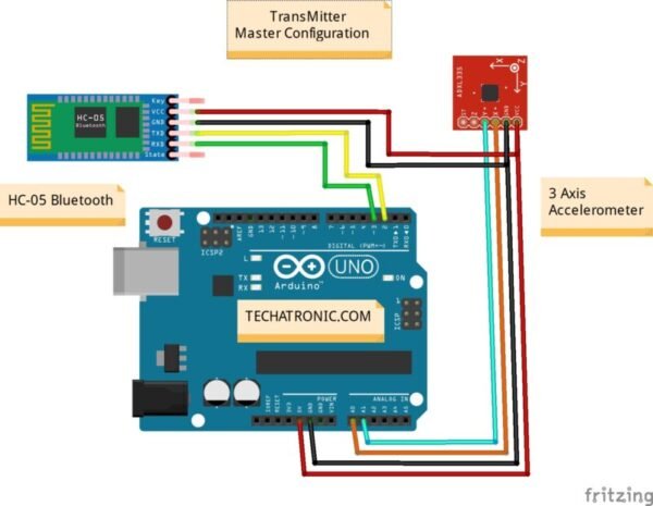
| Arduino UNO | HC-05 Bluetooth |
| ( +5V ) | VCC |
| GND | GND |
| D3 Pin | RX Pin |
| D2 Pin | TX Pin |
| Arduino UNO | 3 Axis Accelerometer |
| ( +5V ) | VCC |
| GND | GND |
| A0 Pin | X |
| A1 Pin | Y |
Now we are also giving the code for both.
Gesture control robot Arduino Code.
Receiver code.
//Receiver code
//all the best
#include<SoftwareSerial.h>
SoftwareSerial mybt(2,3);
char m=0,n=0;

void setup() {
pinMode(10, OUTPUT);
pinMode(11, OUTPUT);
pinMode(12, OUTPUT);
pinMode(13, OUTPUT);
Serial.begin(9600);
mybt.begin(9600);
}

void loop() {
if(mybt.available()>0)
{
m= mybt.read();
Serial.println(m);
if(m=='F')

{
digitalWrite(10, HIGH);
digitalWrite(11, LOW);
digitalWrite(12, HIGH);
digitalWrite(13, LOW);

}

else if(m=='B')

{
digitalWrite(10, LOW);
digitalWrite(11, HIGH);
digitalWrite(12, LOW);
digitalWrite(13, HIGH);

}

else if(m=='R')

{
digitalWrite(10, LOW);
digitalWrite(11, HIGH);
digitalWrite(12, HIGH);
digitalWrite(13, LOW);

}
else if(m=='L')

{
digitalWrite(10, HIGH);
digitalWrite(11, LOW);
digitalWrite(12, LOW);
digitalWrite(13, HIGH);

}

else if(m=='N')

{
digitalWrite(10, LOW);
digitalWrite(11, LOW);
digitalWrite(12, LOW);
digitalWrite(13, LOW);

}
else

{
digitalWrite(10, LOW);
digitalWrite(11, LOW);
digitalWrite(12, LOW);
digitalWrite(13, LOW);

}

} }
Transmitter Code.
//transmitter code
//all the best
#include
SoftwareSerial mybt(2,3);
int m=0, n=0;

void setup() {

pinMode(A0, INPUT);
pinMode(A1, INPUT);
mybt.begin(9600);
Serial.begin(9600);
}

void loop() {
m = analogRead(A0);
n = analogRead(A1);

//Serial.println(m);
//delay(500);
//Serial.println(n);
//delay(500);

if(n>=375)

{
mybt.write("F");
Serial.println("F");

}

else if(n<=320) { mybt.write("B"); Serial.println("B"); } else if(m>=375)
{
mybt.write("R");
Serial.println("R");

}

else if(m<=315)
{
mybt.write("L");
Serial.println("L");

}

else
{
mybt.write("N");
Serial.println("N");

}
}
Upload the code into the transmitter and receiver by the Arduino IDE.
and subscribe us on youtube
Watch this full video on youtube