
Hey guys, hope you are doing fine. We are back with another new project on 555 timer ic. In this post, we are going to make an Ambulance siren project. Along with the ic, we are also using an NPN and a PNP transistor. We are giving the step by step instructions on how you can make your own wailing siren circuit. You can also read more articles on Arduino and IoT published by us. So are you ready to make this circuit? this can be your 555 timers mini project which can be easily done.
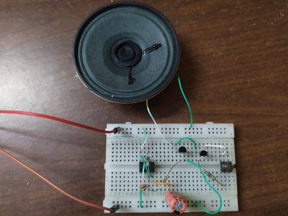
Table of Contents
Introduction to 555 timer mini project
We are using a 555 timer IC for this mini project and two transistors for making this Ambulance siren project. This is a wailing siren so when you press the button it goes on at full volume and slows down with time. These kinds of sirens are used for making alert systems. You can change the values of the resistors and capacitors that we used in this project but don’t change the connections of the IC and transistors.
Connect a 5 volts supply to the positive and negative rails of the breadboard. We are using Bc547 and BC557 transistors which provide accurate current and power to the circuit. There is a push button, and you can press it to ring the buzzer. You can also check out our project on cell phone signal jammer using 555 timer ic. Make the connections on the breadboard as shown in the given diagram.
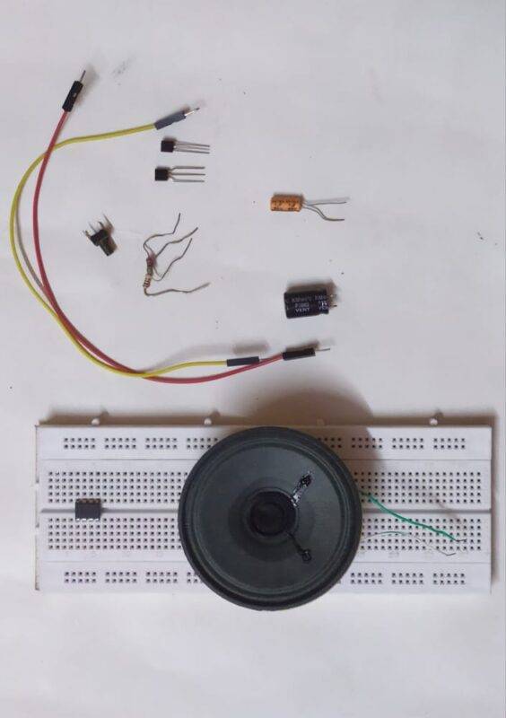
Components Required for Ambulance siren project
| 555 timer ic | BUY LINK |
| pushbutton | BUY LINK |
| resistors 22K, 100K, 33K, 220K, 220K, 39R | BUY LINK |
| Transistors BC547, BC557 | BUY LINK |
| Capacitors 100uF, 10nF, | BUY LINK |
| Breadboard | BUY LINK |
| connecting wires | BUY LINK |
| Speaker | BUY LINK |
you can buy all components together-BUY LINK
Ambulance siren project 555 timer Circuit Diagram
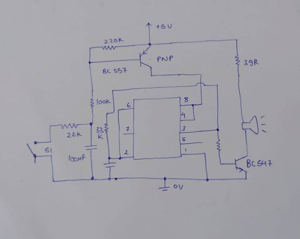
- Place the 555 timer on the breadboard and note the position of its pins.
- Connect pin 1 to the negative rail of the breadboard.
- Put a wire between pins 2 and 6. Connect pins 4 and 8 with each other.
- Now place a 33-k ohm resistor between pins 3 and 6.
- Join the pin 2 and negative rail with a 10 nF capacitor.
- Place an NPN transistor (BC547) on the breadboard and connect the emitter pin to the negative rail of the breadboard.
- Join the base of the transistor and pin 3 of the 555 timer is via a 1K ohm resistor.
- Then take a speaker and connect one wire of it with the collector pin of the transistor and the other wire with the positive rail.
- Put a PNP transistor on the breadboard and connect the collector pin with pin 4 of the IC.
- Attach the emitter pin to the positive rail.
- Join the base and emitter pins via a 220-ohm resistor.
- Take a pushbutton and connect the base pin to one of its interconnect pins.
- Connect the other pin to the negative rail as shown in the diagram.
- Now place a 100 nF capacitor such that its positive leg is connected to the base of the transistor and its negative leg with the negative rail.
Let’s Test the Circuit
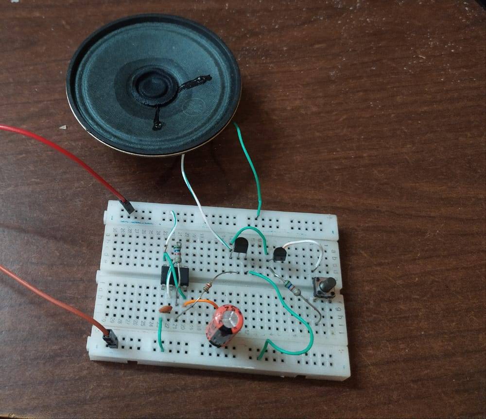
We hope that you liked this project and if so then please try to make it on your own. If you have any suggestions or queries regarding the project then ping us in the comments section given below. You can also check out our tutorials on Arduino and Raspberry Pi.
Thanks for reading.