
In this tutorial, we will be exploring the combination of two popular technologies in the world of embedded systems: the ESP32 microcontroller and the RC522 RFID reader.
Table of Contents
Introduction to ESP32 and RFID
The ESP32 is a powerful microcontroller that can be programmed using the Arduino IDE, and the RC522 RFID reader is a low-cost solution for adding RFID capabilities to your projects. By combining these two ESP32 with RFID technologies, we can create powerful projects that can identify and interact with RFID tags.
In this tutorial, we will be providing a step-by-step guide on how to set up the ESP32 and the RC522 RFID reader, and we will also be providing a sample code that you can use to test the setup. RFID can be used in many projects. where you need a security you can add the RFID module.
Components Required for RFID ESP32
To follow this tutorial, you will need the following hardware:
| ESP32 development board | BUY LINK |
| RC522 RFID reader module | BUY LINK |
| Breadboard | BUY LINK |
| jumper wires | BUY LINK |
| RFID tags | BUY LINK |
| RGB LED | BUY LINK |
| ESP32 Compatible cable | BUY LINK |
all these are components you should have. if you don’t have any experience with working all these sensors. you can find the tutorials on our website.
Software Requirements
To program the ESP32 and the RC522 RFID reader, we will be using the Arduino IDE. Make sure that you have the following software installed:
- Arduino IDE
- ESP32 board package for Arduino IDE
- MFRC522 library for Arduino IDE
You need to install all this software on your computer. and set up the software as we have given the link below section. also, you need many libraries to initiate the setup.
ESP32 with RFID Circuit Diagram
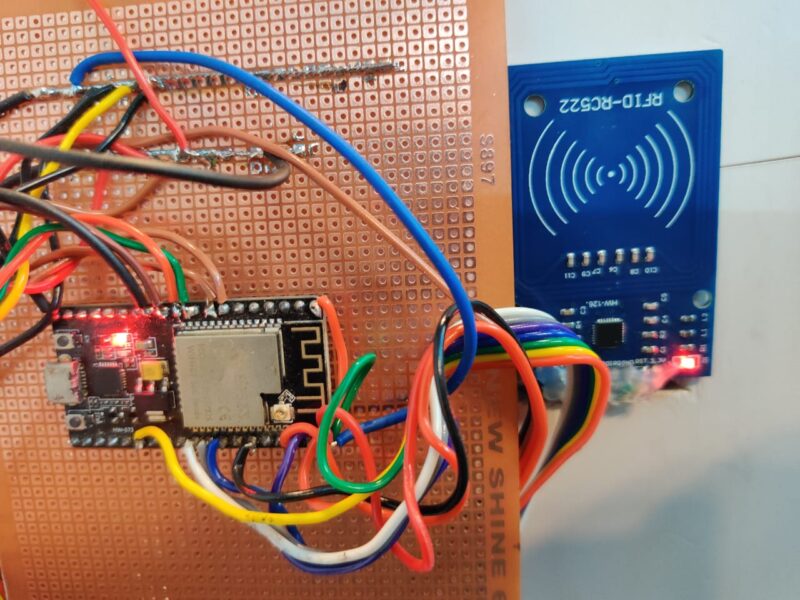
Before we can start programming the ESP32 and the RC522 RFID reader, we need to connect them together. The following diagram shows the wiring diagram for connecting the ESP32 and the RC522 RFID reader:
ESP32            RC522 RFID Reader
-----------------------------------
3V3              3.3V
GND              GND
22 (SCK)         SCK
21 (MOSI)        MOSI
19 (MISO)        MISO
0 (SS)          SDA
The SCK, MOSI, MISO, and SDA pins on the RC522 RFID reader should be connected to the corresponding pins on the ESP32. The 3.3V and GND pins should also be connected to their respective pins on the ESP32.
how to install MFRC522 Library
To make it easier to interact with the RC522 RFID reader, we will be using the MFRC522 library. To install the MFRC522 library, follow these steps:
- Open the Arduino IDE.
- Click on Sketch > Include Library > Manage Libraries.
- In the search bar, search for “MFRC522”.
- Click on the MFRC522 library and click the “Install” button.
ESP32 with RFID RC522 Code | Code in c/c++
Now that we have the ESP32 and the RC522 RFID reader connected and the MFRC522 library installed, we can start writing the code. The following code is an example of how to read an RFID tag and print the UID (Unique Identifier) to the serial monitor:
#include <SPI.h>
#include <MFRC522.h>

#define SS_PIN 5
#define RST_PIN 0

MFRC522 rfid(SS_PIN, RST_PIN); // Instance of the class

MFRC522::MIFARE_Key key;

// Init array that will store new NUID
byte nuidPICC[4];

void setup() {
  Serial.begin(9600);
  SPI.begin(); // Init SPI bus
  rfid.PCD_Init(); // Init MFRC522

  for (byte i = 0; i < 6; i++) {
    key.keyByte[i] = 0xFF;
  }

  Serial.println(F("This code scan the MIFARE Classsic NUID."));
  Serial.print(F("Using the following key:"));
  printHex(key.keyByte, MFRC522::MF_KEY_SIZE);
}

void loop() {

  // Reset the loop if no new card present on the sensor/reader. This saves the entire process when idle.
  if ( ! rfid.PICC_IsNewCardPresent())
    return;

  // Verify if the NUID has been readed
  if ( ! rfid.PICC_ReadCardSerial())
    return;

  Serial.print(F("PICC type: "));
  MFRC522::PICC_Type piccType = rfid.PICC_GetType(rfid.uid.sak);
  Serial.println(rfid.PICC_GetTypeName(piccType));

  // Check is the PICC of Classic MIFARE type
  if (piccType != MFRC522::PICC_TYPE_MIFARE_MINI &&
    piccType != MFRC522::PICC_TYPE_MIFARE_1K &&
    piccType != MFRC522::PICC_TYPE_MIFARE_4K) {
    Serial.println(F("Your tag is not of type MIFARE Classic."));
    return;
  }

  if (rfid.uid.uidByte[0] != nuidPICC[0] ||
    rfid.uid.uidByte[1] != nuidPICC[1] ||
    rfid.uid.uidByte[2] != nuidPICC[2] ||
    rfid.uid.uidByte[3] != nuidPICC[3] ) {
    Serial.println(F("A new card has been detected."));

    // Store NUID into nuidPICC array
    for (byte i = 0; i < 4; i++) {
      nuidPICC[i] = rfid.uid.uidByte[i];
    }

    Serial.println(F("The NUID tag is:"));
    Serial.print(F("In hex: "));
    printHex(rfid.uid.uidByte, rfid.uid.size);
    Serial.println();
    Serial.print(F("In dec: "));
    printDec(rfid.uid.uidByte, rfid.uid.size);
    Serial.println();
  }
  else Serial.println(F("Card read previously."));

  // Halt PICC
  rfid.PICC_HaltA();

  // Stop encryption on PCD
  rfid.PCD_StopCrypto1();
}


/**
 * Helper routine to dump a byte array as hex values to Serial.
 */
void printHex(byte *buffer, byte bufferSize) {
  for (byte i = 0; i < bufferSize; i++) {
    Serial.print(buffer[i] < 0x10 ? " 0" : " ");
    Serial.print(buffer[i], HEX);
  }
}

/**
 * Helper routine to dump a byte array as dec values to Serial.
 */
void printDec(byte *buffer, byte bufferSize) {
  for (byte i = 0; i < bufferSize; i++) {
    Serial.print(buffer[i] < 0x10 ? " 0" : " ");
    Serial.print(buffer[i], DEC);
  }
}
The above-given code is to detect the code inside the card. you need to tap your card on the RFID reader.
note down the code you will get from the serial monitor.
tap your card to the RFID
note down the code you will get.
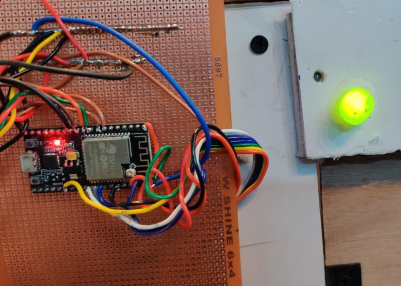
write the next code which will be the final code. so, here we are controlling the RGB led with the card. if you tap the wrong card the LED will be RED or if you place the Right Card the LED will be Green.
#include "SPI.h"
#include "MFRC522.h"
#define SS_PIN 5
#define RST_PIN 0
int m=0,n=0;
#include <ESP32Servo.h>
MFRC522 rfid(SS_PIN, RST_PIN);
MFRC522::MIFARE_Key key;
#define ACCESS_DELAY 2000
#define DENIED_DELAY 1000
#include <LiquidCrystal_I2C.h>
// set the LCD number of columns and rows
int lcdColumns = 16;
int lcdRows = 2;
Servo myservo; // create servo object to control a servo
int pos = 0;
LiquidCrystal_I2C lcd(0x27, lcdColumns, lcdRows);
// initialize the library by associating any needed LCD interface pin
// with the arduino pin number it is connected to
void setup()
{
Serial.begin(9600); // Initiate a serial communication
SPI.begin(); // Initiate SPI bus
//mfrc522.PCD_Init(); // Initiate MFRC522
rfid.PCD_Init();
lcd.init();
myservo.attach(32);
Serial.println("Put your card to the reader...");
lcd.backlight();
lcd.setCursor(0, 1);
lcd.print("Put your card");
Serial.println();
//digitalWrite(RELAY, HIGH);
myservo.write(90);
delay(500);
pinMode(33, INPUT_PULLUP);
pinMode(25, OUTPUT);
pinMode(26, OUTPUT);
//pinMode(A0, INPUT_PULLUP);
pinMode(27, OUTPUT);
pinMode(14, OUTPUT);
//pinMode(14, OUTPUT);
// analogWrite(3, 5);
digitalWrite(26, LOW);
digitalWrite(25, HIGH);
}
void loop()
{
lcd.backlight();
lcd.clear();
Serial.println("Put your card to the reader...");
lcd.setCursor(0, 1);
lcd.print("Put your card");
Serial.println();
// Look for new cards
if (!rfid.PICC_IsNewCardPresent() || !rfid.PICC_ReadCardSerial())
return;
// Serial.print(F("PICC type: "));
MFRC522::PICC_Type piccType = rfid.PICC_GetType(rfid.uid.sak);
// Serial.println(rfid.PICC_GetTypeName(piccType));
// Check is the PICC of Classic MIFARE type
if (piccType != MFRC522::PICC_TYPE_MIFARE_MINI &&
piccType != MFRC522::PICC_TYPE_MIFARE_1K &&
piccType != MFRC522::PICC_TYPE_MIFARE_4K)
{
Serial.println(F("Your tag is not of type MIFARE Classic."));
return;
}
String strID = "";
for (byte i = 0; i < 4; i++) {
strID +=
(rfid.uid.uidByte[i] < 0x10 ? "0" : "") +
String(rfid.uid.uidByte[i], HEX) +
(i!=3 ? ":" : "");
}
strID.toUpperCase();
Serial.print("Tap card key: ");
//delay(1000);
Serial.println(strID);
if(strID.indexOf("11:65:FB:0B")>=0)
{
Serial.println("Authorized access");
lcd.clear();
lcd.setCursor(0, 1);
lcd.print("Authorized access");
Serial.println();
//
myservo.write(180); // tell servo to go to position in variable 'pos'
delay(500);
delay(ACCESS_DELAY);
myservo.write(90);
//delay(500);
while(1)
{
int m= analogRead(33);
Serial.println(m);
// delay(300);
if(m<200)
{
while(1)
{
digitalWrite(26, HIGH);
digitalWrite(14, HIGH);
digitalWrite(25, LOW);
digitalWrite(27, HIGH );
lcd.clear();
lcd.setCursor(0, 1);
lcd.print("Room Occupied");
lcd.setCursor(0, 0);
lcd.print("A Team 3 Members");
analogWrite(3, 225);
delay(200);
}
}
else if (m>500)
{
// analogWrite(3, 10);
digitalWrite(26, LOW);
digitalWrite(25, HIGH);
// digitalWrite(36, LOW );
delay(100);
digitalWrite(14, LOW);
}
}
}
else {
Serial.println(" Access denied");
lcd.clear();
lcd.setCursor(0, 1);
lcd.print("Access denied");
delay(DENIED_DELAY);
// analogWrite(3, 10);
digitalWrite(26, LOW);
digitalWrite(25, HIGH);
// delay(DENIED_DELAY);
digitalWrite(14, LOW);
}
}Upload the given code into the ESP32 with the help of Arduino Ide. here is the tutorial on how to set up esp32 with the Arduino Ide and Program.
I hope you will complete this tutorial easily. and still if you have any problem you can ask in the comment section.