

Hello Tech Folks, I’m back again with another interesting article on Raspberry Pi, Today we’re going to discuss hooking up the How to detect magnetic field. This project is very simple to make and very interesting, also the components used in this tutorial are easily available in the market but the only thing which can be proved costly is Raspberry Pi Board itself(Pi 3B+ using here).
If you’re a beginner, then must visit my Raspberry Pi article series for an introduction to Raspberry Pi Board and Python from scratch.
Table of Contents
What is Linear Hall-Effect Sensor:
The hall-Effect sensor can be the easiest method to detect Magnetic fields in a region. There are many module ranging from the cheapest to the high-priced version of the Hall effect sensor. The version I’m using here is very basic and can be easily found in any online or offline store.
The module has great sensitivity for weak as well as strong magnets. this hall effect sensor we are using. and we will describe how to detect the magnetic field. Also, its sensitivity can be adjusted by tuning the 10k pot available on the module onboard. It gives both types of output, Analog and digital.
To enhance the function of the sensor and to make the analog value available at the output it is paired with an LM393 Op-amp which does a perfect job in both analog and digital signals. The onboard pot(potentiometer) described above actually is connected to a hall effect transistor-type component in series with GND to give a combined signal to the op-amp.
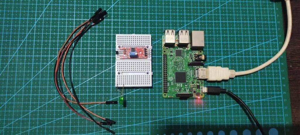
Material Required for detect magnetic field
| S.No | Component Required | Quantity | Buy Link |
| 1. | Raspberry pi 3B+ | 1 | BUY LINK |
| 2. | Raspberry pi Cable | 1 | BUY LINK |
| 3 | USB Mouse & Keyboard | 1 | |
| 4. | Raspberry pi Combo | 1 | BUY LINK |
| 5. | Jumper Wire | 40 | BUY LINK |
| 6. | Breadboard | 1 | BUY LINK |
| 7. | Power supply | 1 | BUY LINK |
| 8. | LED | 1 | BUY LINK |
| 9. | 220 Ohm Resistor | 1 | BUY LINK |
| 10. | Hall Effect Sensor | 1 | BUY LINK |
Circuit Diagram
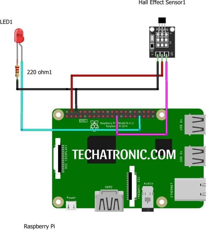
Hall Effect Sensor D0 Pin to Board pin number 11 & LED to pin number 13 of Raspberry Pi according to BOARD numbering
|
Raspberry PI |
Hall Effect Sensor | |
|
GPIO 11 Pin |
D0 | |
|
+5V | +5 V, VCC | |
|
GND |
GND | |
|
Raspberry PI |
LED | 220-ohm Resistor |
|
GPIO 13 Pin |
Anode Terminal ( + ) |
|
|
GND |
|
Terminal 1 |
|
|
Cathode Terminal ( – ) |
Terminal 2 |
Hall effect Python Code
Explanation
From the beginning, if we observe the code then we’ll see that n the first two ones we have imported two important modules in the program RPI & time module which is useful and import for defining pins and time for calculation of time(sleep).
Then from the next line, we define pin mode which can be altered from BOARD or BCM, the difference between the two is clearly defined in my previous articles. For more clarification, visit my series of Raspberry Pi mentioned above.
Then in the while loop, we give the main code which performs all conditions.
Code
 import RPi.GPIO as gp
 from time import sleep
 gp.setmode(gp.BOARD)
 gp.setup(11,gp.IN)
 gp.setup(13,gp.OUT)
 while True:
   try:
     if gp.input(11)==1:
       gp.output(13,gp.HIGH)
     elif gp.input(11)==0:
       gp.output(13,gp.LOW)
   except KeyboardInterrupt:
     gp.cleanup()
     break
With this, we have completed our project Hall Effect Sensor RPI. I hope you enjoyed it and for any queries comment down below.