
Home automation systems are widely used in smart homes nowadays. There are several types of automation systems like mobile phone control, google control, and Alexa control but this time we have made this esp8266 Alexa home automation system with All. like you can control the home with google home, Alexa, manual or mobile too.
This ESP8266 Alexa home automation system is very useful and advanced. Home automation systems can be bought from companies. there are many companies that are making home automation systems. but this time we brought the full instructions to make this on your own. You can make this system by yourself instead of buying them. because they are very costly.
Introduction:-
For this system working we need a small microcontroller that has inbuilt wifi. ESP8266 is can do at the same time. it is a microcontroller with inbuilt wifi. only we need an internet connection to operate this controller. In this system first, we need a mobile phone with two applications one is google home and the other is Alexa. both apps can control the esp8266 Alexa home automation. we need to install the application and configure the applications.
Alexa home automation with Nodemcu is very simple to understand and use. We have also added the manual keys feature. if in any case, the internet is not working then we can control the appliances with the manual keys. We are going to add this home automation system to our home appliances. It won’t be easy if you are not an electrician expert then, don’t do that. Hire an electrician who can help you with that. So, now we are going to start making our ESP8266-based home automation.
Constructions
To make this awesome home automation project we need to follow the given steps and instructions. first, we need to make the circuit diagram. and then code. and some configuration in mobile and the server. so, let’s get started.
Components Required:

Code
before upload this code you need to download the given library.
- Sinric Pro
- ArduinoJson
- WebSockets
/**********************************************************************************
 *  TITLE: Google + Alexa + Manual Switch/Button control 4 Relays using ESP32 & Sinric Pro (Real time feedback)
 *  (flipSwitch can be a tactile button or a toggle switch) (code taken from Sinric Pro examples then modified)
 *  Click on the following links to learn more.
 *  YouTube Video: https://youtu.be/QGpZmZB9g5g
 *  Related Blog : https://iotcircuithub.com/esp32-projects/
 *  by Tech StudyCell
 *  Preferences--> Aditional boards Manager URLs :
 *  https://dl.espressif.com/dl/package_esp32_index.json, http://arduino.esp8266.com/stable/package_esp8266com_index.json
 *
 *  Download Board ESP32 : https://github.com/espressif/arduino-esp32
 *  Download the libraries
 *  ArduinoJson Library: https://github.com/bblanchon/ArduinoJson
 *  arduinoWebSockets Library: https://github.com/Links2004/arduinoWebSockets
 *  SinricPro Library: https://sinricpro.github.io/esp8266-esp32-sdk/
 *
 *  If you encounter any issues:
 * - check the readme.md at https://github.com/sinricpro/esp8266-esp32-sdk/blob/master/README.md
 * - ensure all dependent libraries are installed
 *   - see https://github.com/sinricpro/esp8266-esp32-sdk/blob/master/README.md#arduinoide
 *   - see https://github.com/sinricpro/esp8266-esp32-sdk/blob/master/README.md#dependencies
 * - open serial monitor and check whats happening
 * - check full user documentation at https://sinricpro.github.io/esp8266-esp32-sdk
 * - visit https://github.com/sinricpro/esp8266-esp32-sdk/issues and check for existing issues or open a new one
 **********************************************************************************/

// Uncomment the following line to enable serial debug output
//#define ENABLE_DEBUG


#ifdef ENABLE_DEBUG
       #define DEBUG_ESP_PORT Serial
       #define NODEBUG_WEBSOCKETS
       #define NDEBUG
#endif

#include <Arduino.h>
#include <WiFi.h>
#include "SinricPro.h"
#include "SinricProSwitch.h"

#include <map>

#define WIFI_SSID         "Ersaab_2.4"
#define WIFI_PASS         "Coachsaab.23"
#define APP_KEY           "3dfbe3e3-7a03-48d4-9a59-782186e96197"      // Should look like "de0bxxxx-1x3x-4x3x-ax2x-5dabxxxxxxxx"
#define APP_SECRET        "7f725305-e1d3-4f36-80b3-c4f01b3635c8-73aaa849-4eb5-432e-bbfb-b53bca3f3994"   // Should look like "5f36xxxx-x3x7-4x3x-xexe-e86724a9xxxx-4c4axxxx-3x3x-x5xe-x9x3-333d65xxxxxx"

//Enter the device IDs here
#define device_ID_1   "62ac0857fce0b9e02e712477"
#define device_ID_2   "62ac089afb740f77fc1040ad"
#define device_ID_3   "62ac08b6fb740f77fc1040d3"
#define device_ID_4   "SWITCH_ID_NO_4_HERE"

// define the GPIO connected with Relays and switches
#define RelayPin1 23  //D23
#define RelayPin2 22  //D22
#define RelayPin3 21  //D21
#define RelayPin4 19  //D19

#define SwitchPin1 13  //D13
#define SwitchPin2 12  //D12
#define SwitchPin3 14  //D14
#define SwitchPin4 27  //D27

#define wifiLed   2   //D2

// comment the following line if you use a toggle switches instead of tactile buttons
//#define TACTILE_BUTTON 1

#define BAUD_RATE   9600

#define DEBOUNCE_TIME 250

typedef struct {      // struct for the std::map below
  int relayPIN;
  int flipSwitchPIN;
} deviceConfig_t;


// this is the main configuration
// please put in your deviceId, the PIN for Relay and PIN for flipSwitch
// this can be up to N devices...depending on how much pin's available on your device ;)
// right now we have 4 devicesIds going to 4 relays and 4 flip switches to switch the relay manually
std::map<String, deviceConfig_t> devices = {
    //{deviceId, {relayPIN,  flipSwitchPIN}}
    {device_ID_1, {  RelayPin1, SwitchPin1 }},
    {device_ID_2, {  RelayPin2, SwitchPin2 }},
    {device_ID_3, {  RelayPin3, SwitchPin3 }},
    {device_ID_4, {  RelayPin4, SwitchPin4 }}
};

typedef struct {      // struct for the std::map below
  String deviceId;
  bool lastFlipSwitchState;
  unsigned long lastFlipSwitchChange;
} flipSwitchConfig_t;

std::map<int, flipSwitchConfig_t> flipSwitches;    // this map is used to map flipSwitch PINs to deviceId and handling debounce and last flipSwitch state checks
                                                  // it will be setup in "setupFlipSwitches" function, using informations from devices map

void setupRelays() {
  for (auto &device : devices) {           // for each device (relay, flipSwitch combination)
    int relayPIN = device.second.relayPIN; // get the relay pin
    pinMode(relayPIN, OUTPUT);             // set relay pin to OUTPUT
    digitalWrite(relayPIN, HIGH);
  }
}

void setupFlipSwitches() {
  for (auto &device : devices)  {                     // for each device (relay / flipSwitch combination)
    flipSwitchConfig_t flipSwitchConfig;              // create a new flipSwitch configuration

    flipSwitchConfig.deviceId = device.first;         // set the deviceId
    flipSwitchConfig.lastFlipSwitchChange = 0;        // set debounce time
    flipSwitchConfig.lastFlipSwitchState = true;     // set lastFlipSwitchState to false (LOW)--

    int flipSwitchPIN = device.second.flipSwitchPIN;  // get the flipSwitchPIN

    flipSwitches[flipSwitchPIN] = flipSwitchConfig;   // save the flipSwitch config to flipSwitches map
    pinMode(flipSwitchPIN, INPUT_PULLUP);                   // set the flipSwitch pin to INPUT
  }
}

bool onPowerState(String deviceId, bool &state)
{
  Serial.printf("%s: %s\r\n", deviceId.c_str(), state ? "on" : "off");
  int relayPIN = devices[deviceId].relayPIN; // get the relay pin for corresponding device
  digitalWrite(relayPIN, !state);             // set the new relay state
  return true;
}

void handleFlipSwitches() {
  unsigned long actualMillis = millis();                                          // get actual millis
  for (auto &flipSwitch : flipSwitches) {                                         // for each flipSwitch in flipSwitches map
    unsigned long lastFlipSwitchChange = flipSwitch.second.lastFlipSwitchChange;  // get the timestamp when flipSwitch was pressed last time (used to debounce / limit events)

    if (actualMillis - lastFlipSwitchChange > DEBOUNCE_TIME) {                    // if time is > debounce time...

      int flipSwitchPIN = flipSwitch.first;                                       // get the flipSwitch pin from configuration
      bool lastFlipSwitchState = flipSwitch.second.lastFlipSwitchState;           // get the lastFlipSwitchState
      bool flipSwitchState = digitalRead(flipSwitchPIN);                          // read the current flipSwitch state
      if (flipSwitchState != lastFlipSwitchState) {                               // if the flipSwitchState has changed...
#ifdef TACTILE_BUTTON
        if (flipSwitchState) {                                                    // if the tactile button is pressed
#endif
          flipSwitch.second.lastFlipSwitchChange = actualMillis;                  // update lastFlipSwitchChange time
          String deviceId = flipSwitch.second.deviceId;                           // get the deviceId from config
          int relayPIN = devices[deviceId].relayPIN;                              // get the relayPIN from config
          bool newRelayState = !digitalRead(relayPIN);                            // set the new relay State
          digitalWrite(relayPIN, newRelayState);                                  // set the trelay to the new state

          SinricProSwitch &mySwitch = SinricPro[deviceId];                        // get Switch device from SinricPro
          mySwitch.sendPowerStateEvent(!newRelayState);                            // send the event
#ifdef TACTILE_BUTTON
        }
#endif
        flipSwitch.second.lastFlipSwitchState = flipSwitchState;                  // update lastFlipSwitchState
      }
    }
  }
}

void setupWiFi()
{
  Serial.printf("\r\n[Wifi]: Connecting");
  WiFi.begin(WIFI_SSID, WIFI_PASS);

  while (WiFi.status() != WL_CONNECTED)
  {
    Serial.printf(".");
    delay(250);
  }
  digitalWrite(wifiLed, HIGH);
  Serial.printf("connected!\r\n[WiFi]: IP-Address is %s\r\n", WiFi.localIP().toString().c_str());
}

void setupSinricPro()
{
  for (auto &device : devices)
  {
    const char *deviceId = device.first.c_str();
    SinricProSwitch &mySwitch = SinricPro[deviceId];
    mySwitch.onPowerState(onPowerState);
  }

  SinricPro.begin(APP_KEY, APP_SECRET);
  SinricPro.restoreDeviceStates(true);
}

void setup()
{
  Serial.begin(BAUD_RATE);

  pinMode(wifiLed, OUTPUT);
  digitalWrite(wifiLed, LOW);

  setupRelays();
  setupFlipSwitches();
  setupWiFi();
  setupSinricPro();
}

void loop()
{
  SinricPro.handle();
  handleFlipSwitches();
}
Server configuration
Open since pro official website by the given link.
Next, you have to log in or signup to the website
after creating the account you will get an APP key and APP SECRET

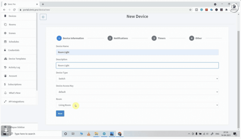
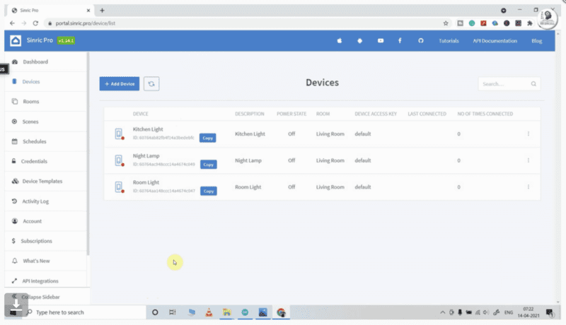
Add a room to your dashboard
After adding room and giving them a name
Then Add devices one by one and give the nickname for each device.
Sinric assigns a unique device ID for each device.
Here, I have used the free Sinric Pro account, so I can add a maximum of 3 devices for free.
Mobile Configuration
First, we will configure google home
and download google home to your mobile.
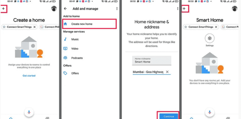
Sign in to the google home
Create a new home
and give a name to the home
Alexa configuration
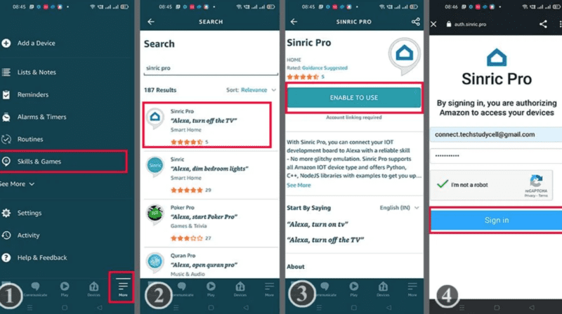
Click on the skill and games
search sinric pro and sign up.
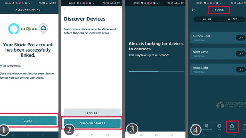
After syncing the Alexa to the sinric pro. Alexa will discover by itself all the details in sinric account you have made.
Working
After completing the configuration in mobile and server. start the ESP8266 Alexa Home Automation System project. when we switch on the system and start the internet on our mobile phone the system starts working.
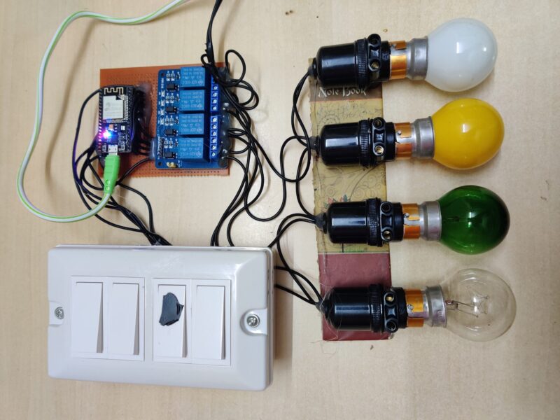
if we want to control the appliance by the manual switch directly we can control it by switching manually. there are 4 switches in our project you can see in this given image. one switch control one appliance.
if you want to control things with Alexa you need to open the Alexa application and operate the appliance with Alexa. also, you can use Alexa chatbox to control this.
last but not least is google home. google home also can control things in this project. so we have made this project to control the home by these 3 ways.
Application
- Smart Home Control: Home automation systems like Alexa and Google Home allow you to control all of your smart devices from one central hub. You can turn lights on and off, control the temperature, lock and unlock doors, and even view live footage from security cameras, all from your voice or through a mobile app.
- Entertainment Control: These systems can also be used to control your entertainment devices such as TVs, sound systems, and streaming devices. With voice commands, you can start playing music, change the channel, or adjust the volume without ever leaving the comfort of your couch.
- Automated Routines: With the ability to set routines and schedules, you can automate your home to perform certain tasks at specific times of the day. For example, you can set a routine to turn off the lights and lock the doors when you leave the house or have the coffee maker start brewing coffee as soon as you wake up.
- Voice-Enabled Shopping: Alexa and Google Home can be used to make shopping easier and more convenient. With voice commands, you can order groceries, purchase items, and have them delivered right to your door.
- Hands-Free Cooking: If you love to cook but hate the mess that comes with it, home automation systems can help. With voice commands, you can start timers, set reminders, and even convert measurements, allowing you to keep your hands free while cooking up a storm.
FAQ
Question: Can I use ESP8266 with both Alexa and Google Home?
Answer: Yes, you can use both simultaneously. for reference you can visit our article.
Question: Can I control my ESP8266 devices using a mobile app?
Answer: Yes you can use esp8266 to control the device refer to this article home automation.
Question: Can I automate routines with ESP8266 and virtual assistants like Alexa and Google Home?
Answer: Yes, you can automate routines with ESP8266 and virtual assistants. You can set schedules for your devices to turn on and off at specific times