Table of Contents
Introduction
Hey Folks, I’m back again with a very interesting and almost most useful project related to irrigation. IoT-based smart irrigation.
People who love gardening feel it very annoying to go every day for the status of their plants. So today we gonna demonstrate how you can get the real-time status of your garden with the help of a few components.
we have made other many projects like blynk home automation. gonna use the NodeMCU and Blynk app for real-time data capture for viewing the status of mostly all things.
So let’s begin!!!!
NodeMCU:
If you are new to this site or a beginner so before starting read this brief info about NodeMCU set up. NodeMCu is basically the same as other microcontrollers like Arduino Uno or Nano.
But it has better speed, flash space, also has in-built Wi-Fi and Bluetooth. There are various models in the market which are very good and have both functionalities.
But today we gonna use the most common version available in the market i.e., NodeMCU (ESP8266MOD).
Also,
it runs on a 3.3v logic level which reduces the chances of the logic level problems we came across various sensors while using the Arduino microcontroller. So to sum up I must say that it is pretty much everything for a beginner in the IoT field.
Remember to download the CH340 driver for this module as sometimes it doesn’t get detected on a computer or laptop at first. To install it from here.
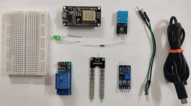
Material Required:
| NodeMCU (ESP8266MOD) | BUY LINK |
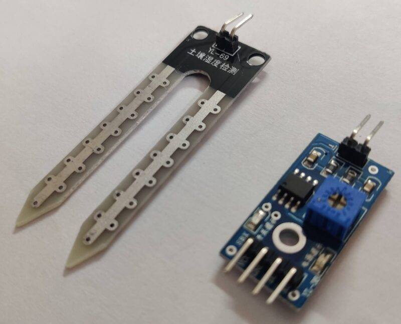
| Soil Moisture sensor | BUY LINK |
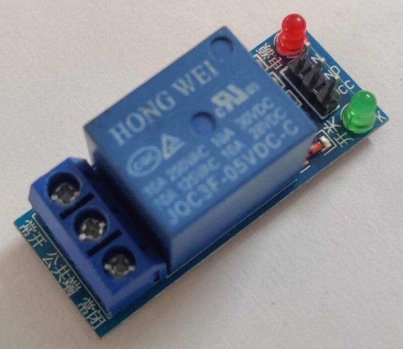
| Relay module | BUY LINK |
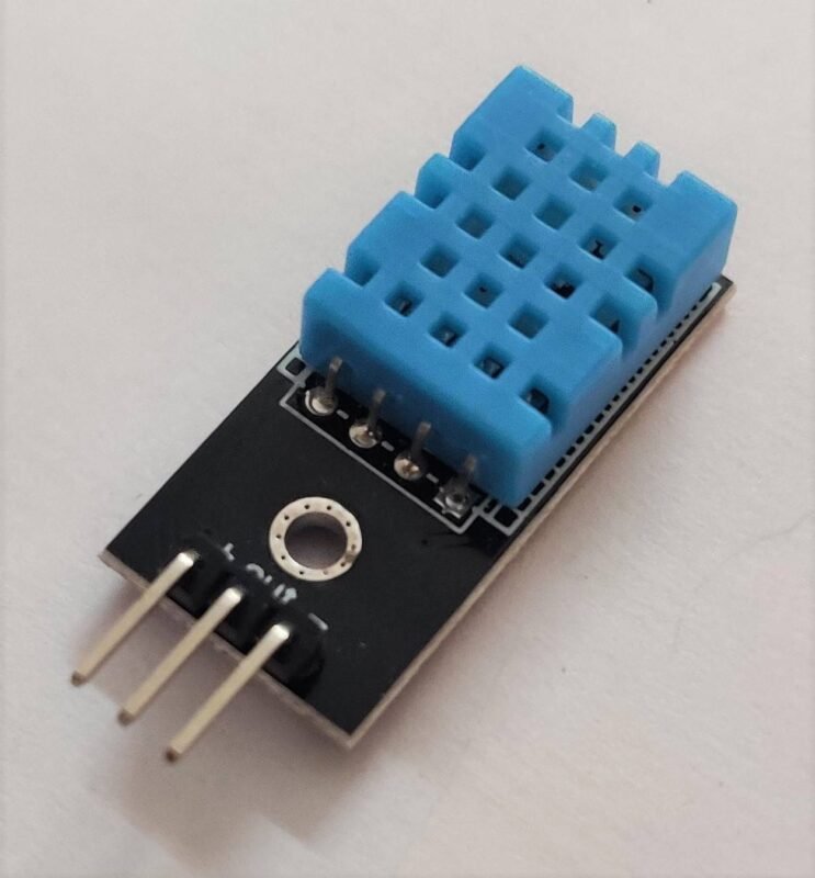
| DHT11 sensor | BUY LINK |
| water pump | BUY LINK |
| green LED | BUY LINK |
| Resistor | BUY LINK |
| 12V supply | BUY LINK |
| Breadboard | BUY LINK |
| Jumper wire | BUY LINK |
IoT smart irrigation Circuit Diagram:
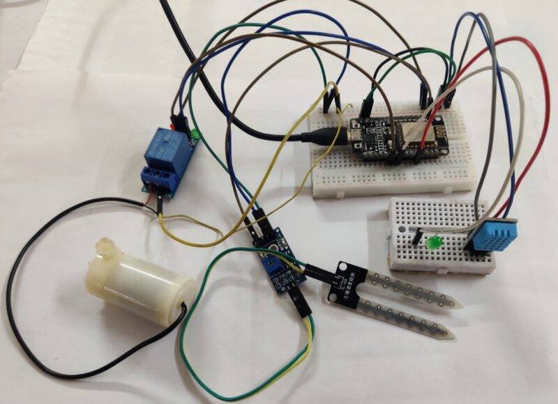
There are two sensors and motor, led interfaced with the nodemcu. it is a very good project for learning. there is all the connections that are clear and easy to make. still, you have any doubt you can ask in the comments.
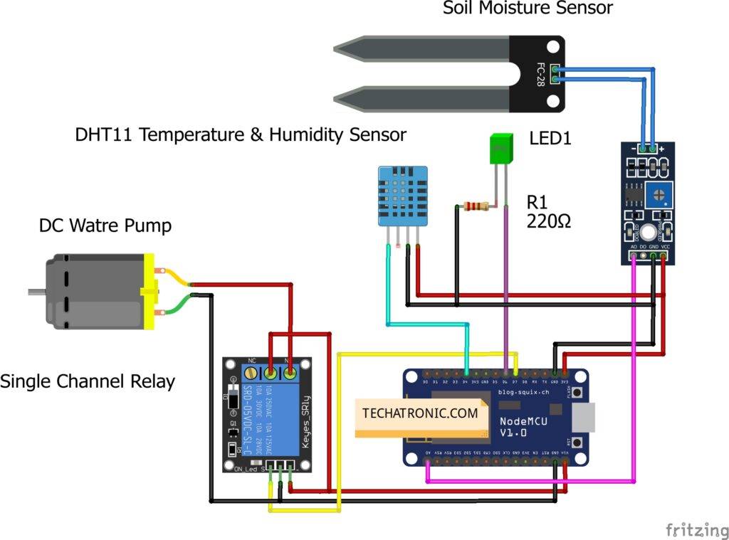
Connection Table
| Nodemcu esp8266 | Dht11 Sensor | |
| VV, Vin | ( V ) VCC | |
| G, GND | ( G ) GND | |
| D4 Pin | ( S ) OUT Pin | |
| Nodemcu esp8266 | Soil Moisture Sensor | |
| VV, Vin | VCC | |
| G, GND | GND | |
| A0 Pin | ( A0 ) OUT Pin | |
| Nodemcu esp8266 | 5V Single Channel Relay | |
| VV, Vin | VCC | |
| G, GND | GND | |
| D7 Pin | ( S ) OUT Pin | |
| 12 Volt Adaptor | Water Pump | 5V Single Channel Relay |
| Normally Open | ||
| + Positive | Common | |
| Terminal 1 | Normally Closed | |
| Negative | Terminal 2 | |
| Nodemcu | LED | 220 Ohm resistor |
| D6 Pin | Anode Terminal | |
| G, GND | Terminal 1 | |
| Cathode Terminal | Terminal 2 |
PIN CONNECTIONS:
DHT11 —> D4
Soil-moisture —> A0
LED —> D6
Realy —> D7
rest are VCC and GND connections
IoT smart irrigation Code:
In the beginning, we include some libraries which are required in this project. Then we assign pins to which both sensor, including led and relay, is connected. Along with this we also store our auth key received on email and wifi SSID & password.
After that, we create a function named send sensor() to check the DHT11 sensor and read the value of temperature and humidity from it. Also if a sensor fails to get these values it displays an error message on the serial monitor.
 void sendSensor()
 {
  float h = dht.readHumidity();
  float t = dht.readTemperature();
  if (isnan(h) || isnan(t)) {
   Serial.println("Failed to read from DHT sensor!");
   return;
  }
  Blynk.virtualWrite(V5, h); //V5 is for Humidity
  Blynk.virtualWrite(V6, t); //V6 is for Temperature
 }
Then we begin our setup() loop to initialize connection to our wifi and begin transmission between blynk app and NodeMCU. also
initializes the DHT11sensor.
 void setup()
 {
  Serial.begin(9600);
  Blynk.begin(auth, ssid, pass);
  dht.begin();
  timer.setInterval(1000L, sendSensor);
  Serial.begin(115200);
  Blynk.begin(auth, ssid, pass);
   sensors.begin();
 }
Then we create another function senstemp() to check values from all sensor i.e., DHT11 and soil-moisture.
 void sendTemps()
 {
 sensor=analogRead(A0);
 sensors.requestTemperatures();
 float temp = sensors.getTempCByIndex(0);
 Serial.println(temp);
 Serial.println(sensor);
 Blynk.virtualWrite(V1, temp);
 Blynk.virtualWrite(V2,sensor);
 delay(1000);
 }
Then we run all these codes in loop()
Here is
complete code:
 //TECHATRONIC.COM
 // BLYNK LIBRARY
 // https://github.com/blynkkk/blynk-library
 // ESP8266 LIBRARY
 // https://github.com/ekstrand/ESP8266wifi
 // DHT11 SENSOR LIBRARY
 // https://github.com/adafruit/DHT-sensor-library
 #define BLYNK_PRINT Serial
 #include <SPI.h>
 #include <ESP8266WiFi.h>
 #include <BlynkSimpleEsp8266.h>
 #include <SimpleTimer.h>
 #include <DHT.h>
 #define BLYNK_PRINT Serial
 #include <OneWire.h>
 #include <DallasTemperature.h>
 #define ONE_WIRE_BUS D2
 OneWire oneWire(ONE_WIRE_BUS);
 DallasTemperature sensors(&oneWire);
 char auth[] =" your auth code";
 char ssid[] = "your wifi ssid";
 char pass[] = "your wifi password";
 #define DHTPIN 2
 #define DHTTYPE DHT11   // DHT11 SENSOR CONNECT D4 PIN
 DHT dht(DHTPIN, DHTTYPE);
 SimpleTimer timer;
 void sendSensor()
 {
  float h = dht.readHumidity();
  float t = dht.readTemperature();
  if (isnan(h) || isnan(t)) {
   Serial.println("Failed to read from DHT sensor!");
   return;
  }
  Blynk.virtualWrite(V5, h); //V5 is for Humidity
  Blynk.virtualWrite(V6, t); //V6 is for Temperature
 }
 void setup()
 {
  Serial.begin(9600);
  Blynk.begin(auth, ssid, pass);
  dht.begin();
  timer.setInterval(1000L, sendSensor);
  Serial.begin(115200);
  Blynk.begin(auth, ssid, pass);
   sensors.begin();
 }
 int sensor=0;
 void sendTemps()
 {
 sensor=analogRead(A0);
 sensors.requestTemperatures();
 float temp = sensors.getTempCByIndex(0);
 Serial.println(temp);
 Serial.println(sensor);
 Blynk.virtualWrite(V1, temp);
 Blynk.virtualWrite(V2,sensor);
 delay(1000);
 }
 void loop()
 {
  Blynk.run();
  timer.run();
  sendTemps();
 }
Blynk App setup & installation:
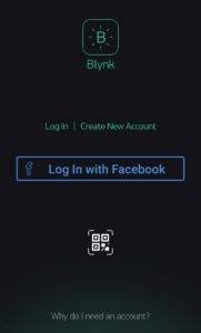
Download and install Blynk app from any App store Playstore | Apple appstore . Also login into App
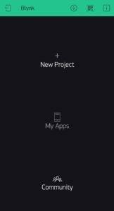
You will see main screen after logging into the app
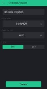
Then create a new project with any of your desired name(IoT base irrigation here)
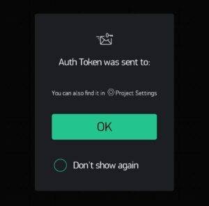
An authentication token will be sent to your registered Email-ID. View the mail and copy & paste it in the code where auth key is required. Also fill up your Wi-Fi details so that Blynk app and NodeMCU can communicate.
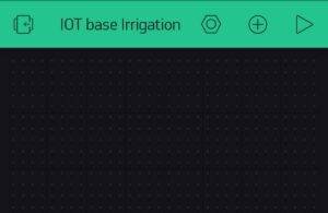
You’ll see this type of screen after creating a project
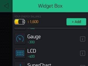
Now add some Widgets to get the value from NodeMCU.
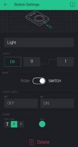
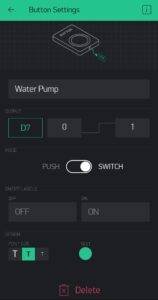
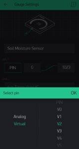
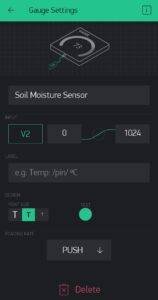
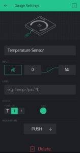
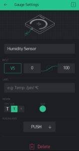
Add all eidgets as directed in above pictures
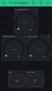
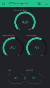
After completion you’ll see this type of interface
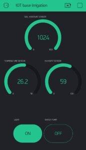
Now you are ready to grab values and control pump and light with Blynk app
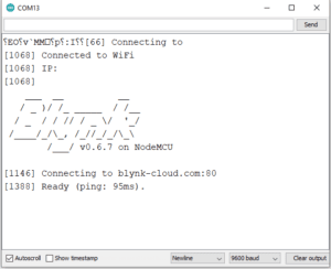
You will see this type of output in serial monitor, If your connection is successful.
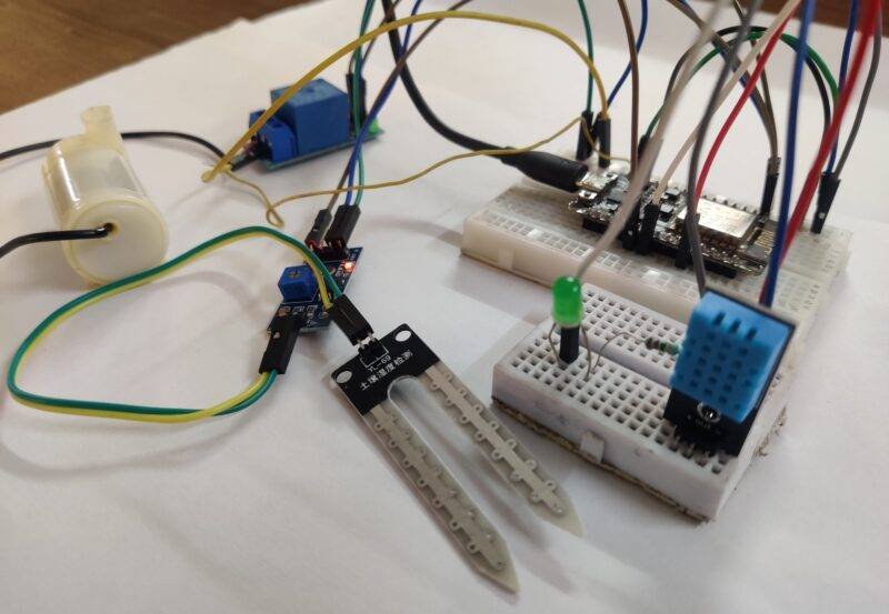
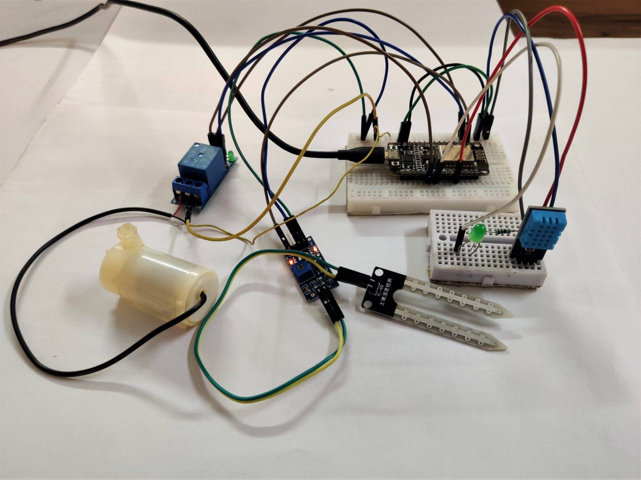
With this we have completed our IoT based smart irrigation project. Enjoy it & if you face any problem then ask me below.
Some Related project
Smart Irrigation system Raspberry Pi
Smart Irrigation System using Arduino
Soil Moisture Sensor Working, explanation, Schematic
water level sensor with Arduino | Check Water level sensor with arduino


Bonsoir
Je trouve le projet d’irrigation automatique des plantes très intéressant.
En contre j’aimerais le réaliser moi même….
Je sollicite un document sur ce projet
What is simple timer ?this is my error in coding how to rectify this