

Table of Contents
Introduction
Hi there Folks, Welcome to my other interesting post on IoT which is IoT Weather Monitoring System.
As the name suggests, it tells us weather conditions in our nearby environment. It tells Temperature, Humidity, and Rainfall in our local area.
But the condition can be viewed anywhere in the world through Blynk App. It can be considered useful in the northern region. Greenhouse or personal gardens can be implanted with these solutions for better access to weather conditions.
So let’s begin our journey!!

Modules Used:
DHT11:
This sensor is mainly responsible for Temperature and Humidity. I have already made a detailed article on this sensor with Arduino (Arduino DHT11). You should visit this as a beginner.
Briefly, it simply calculates the resistance between two probes of the sensor. The measurement seems to be nearly accurate, so it can be considered for this project, but you may also use many advanced temperature and humidity sensors.

Rain Sensor:
This sensor is mainly a plain conducting plate that detects rain and then uses an Op-Amp IC which amplifies the signal and then sends it to the microcontroller.
It is built out of LM393 IC, which is a comparator op-amp. It has an onboard potentiometer that can be used to trim the values. Furthermore, it is very easy and simple.
For more information, you can visit Rain Sensor Arduino Tutorial. LM393 IC datasheet.

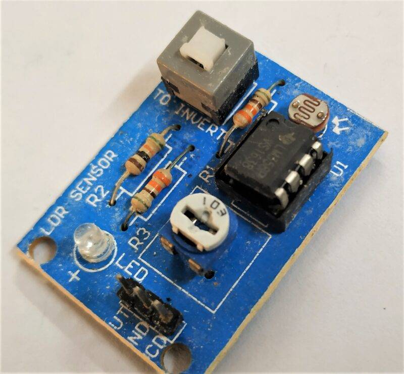
LDR Sensor:
We have also used an LDR sensor for determining the day and night conditions. At daytime, the light of the physical LCD will remain off and on Blynk App it will show Red light off. But at nighttime, the LCD backlight will turn on and the same as on Blynk App.
There are other modules also used like the I2C module and 16 x 2 LCD which are used in this project. They are very easy to use and can be programmed easily. You may see these articles for reference. 16 x 2 LCD, LDR SENSOR, I2C LCD.
Interfacing:
Material Required:
- NodeMCU (EP8266 MOD)
- DHt11
- Rain Sensor
- LDR Sensor
- 16×2 LCD with I2C module
- Breadboard
- Jumper Wires
- Blynk App with Wi-Fi connection
- Battery

IoT Weather station Circuit Diagram
 Connection table:
 Connection table:
| Nodemcu Esp8266 | Rain Drop Sensor |
| A0 Pin | AO Pin |
| Vin, VV | VCC |
| GND | GND |
| Nodemcu Esp8266 | DHT 11 Temperature & Humidity Sensor |
| D3 Pin | S ( Signal ) |
| Vin, VV | V ( VCC ) |
| GND | G ( GND ) |
| Nodemcu Esp8266 | LDR Sensor Module |
| D4 Pin | DO OUT Pin |
| Vin, VV | VCC |
| GND | GND |
| Nodemcu Esp8266 | I2C LCD Module |
| D2 Pin | SDA Pin |
| D1 Pin | SCL Pin |
| Vin, VV | VCC |
| GND | GND |
| 16 * 2 LCD | I2C LCD Module |
| 16 Connect | 16 Connect |
PINOUT
I2C LCD SCL, SDA —> D1, D2
DHT11 —> D3
LDR —> D4
RAIN SENSOR —> A0
IoT Weather station Code
Explanation:
First we include Some basic libraries as always for working of program. Also, we create dht11 and LCD object which stores the connecting information of both.
Now we create custom function weather which reads the Temperature and Humidity from DHT11 and stores it variables. In this, we calculate all values and display it on the physical LCD and Blynk App.
void weather() {
  float h = dht.readHumidity();
  float t = dht.readTemperature();
  int r = analogRead(A0);
  bool l = digitalRead(D4);

  r = map(r, 0, 1023, 100, 0);
  if (isnan(h) || isnan(t)) {
    Serial.println("Failed to read from DHT sensor!");
    return;
  }

  Blynk.virtualWrite(V0, t);  //V0 is for Temperature
  Blynk.virtualWrite(V1, h);  //V1 is for Humidity
  Blynk.virtualWrite(V2, r);  //V2 is for Rainfall

  if (l == 0) {
    WidgetLED led1(V3);
    led1.on();
    lcd.setCursor(9, 1);
    lcd.print("L :");
    lcd.print("High");
    lcd.print(" ");
  } else if (l == 1) {
    WidgetLED led1(V3);
    led1.off();
    lcd.setCursor(9, 1);
    lcd.print("L :");
    lcd.print("Low");
    lcd.print(" ");
  }

  lcd.setCursor(0, 0);
  lcd.print("T :");
  lcd.print(t);

  lcd.setCursor(0, 1);
  lcd.print("H :");
  lcd.print(h);

  lcd.setCursor(9, 0);
  lcd.print("R :");
  lcd.print(r);
  lcd.print("  ");

}
In the IoT project setup section, we define pinMode and start several communications for synchronization. But in the loop, we run two main loops which indirectly run the whole program
Code:
Here is the main code
// TECHATRONIC.COM
// I2C LIBRARY
// https://github.com/fdebrabander/Arduino-LiquidCrystal-I2C-library
// BLYNK LIBRARY
// https://github.com/blynkkk/blynk-library
// ESP8266 LIBRARY
// https://github.com/ekstrand/ESP8266wifi
// Adafruit DHT sensor library:
// https://github.com/adafruit/DHT-sensor-library


#include <LiquidCrystal_I2C.h>
#define BLYNK_PRINT Serial
#include <ESP8266WiFi.h>
#include <BlynkSimpleEsp8266.h>
#include <DHT.h>

LiquidCrystal_I2C lcd(0x3F, 16, 2);
// IF IN LCD IS NOT PRINTED ANY THING THEN CHANGE THIS VALUE 0x3F TO 0x27
DHT dht(D3, DHT11); //(sensor pin,sensor type)
BlynkTimer timer;

char auth[] = " Your-auth-code"; //Enter the Auth code which was send by Blink
char ssid[] = "your-wifi-ssid";  //Enter your WIFI Name
char pass[] = "your-wifi-password";  //Enter your WIFI Password

void weather() {
  float h = dht.readHumidity();
  float t = dht.readTemperature();
  int r = analogRead(A0);
  bool l = digitalRead(D4);

  r = map(r, 0, 1023, 100, 0);
  if (isnan(h) || isnan(t)) {
    Serial.println("Failed to read from DHT sensor!");
    return;
  }

  Blynk.virtualWrite(V0, t);  //V0 is for Temperature
  Blynk.virtualWrite(V1, h);  //V1 is for Humidity
  Blynk.virtualWrite(V2, r);  //V2 is for Rainfall

  if (l == 0) {
    WidgetLED led1(V3);
    led1.on();
    lcd.setCursor(9, 1);
    lcd.print("L :");
    lcd.print("High");
    lcd.print(" ");
  } else if (l == 1) {
    WidgetLED led1(V3);
    led1.off();
    lcd.setCursor(9, 1);
    lcd.print("L :");
    lcd.print("Low");
    lcd.print(" ");
  }

  lcd.setCursor(0, 0);
  lcd.print("T :");
  lcd.print(t);

  lcd.setCursor(0, 1);
  lcd.print("H :");
  lcd.print(h);

  lcd.setCursor(9, 0);
  lcd.print("R :");
  lcd.print(r);
  lcd.print("  ");

}

void setup() {
  Serial.begin(9600); // See the connection status in Serial Monitor
  lcd.begin();
  lcd.backlight();
  Blynk.begin(auth, ssid, pass);
  dht.begin();
  // Setup a function to be called every second
  timer.setInterval(10L, weather);
}

void loop() {
  Blynk.run(); // Initiates Blynk
  timer.run(); // Initiates SimpleTimer
}
Blynk App installation:
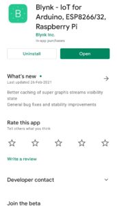
Download and Install Blynk App from your preferred App Store. PlayStore | Apple AppStore.


Create New Project
Log in to the App using your social accounts and email-id. Remember, this email-id will be used for sending Auth-Code.

Now you’ll reach at the main screen from where you’ll control all tasks.
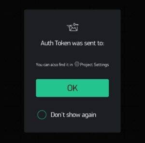
Now create a New Project with your preferred name. Here I have used ‘IoT weather Monitoring’. As soon as you create, an Auth-Code will be sent to your registered email-id.

Now Add widgets to the main screen for displaying and controlling modules

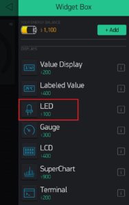


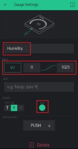

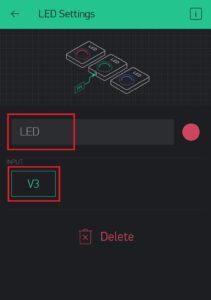
Now set things up as shown in the above images. And now you are good to start collecting information from NodeMCU.

Now click on the Play button to implement the settings.

After that, you may see values are changing both on Blynk App and LCD.
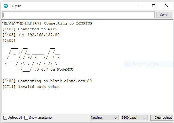
Now power up your NodeMCU and start Serial Monitor. You’ll see output something like this.
There are few final images attached below:
Project sample
Here you can see the sample image that how the system will work with all the setup.


With this, we end our today’s tutorial on IoT Weather Monitoring System. I hope you find it interesting, If you find any issue while performing it then let me know below.