
Hello guys, we are back with another new post in the series of 555 timer projects. Are you searching for a railway signal circuit? Well if yes then you are at the right place. In this article,

we are going to teach you how you can make your own railway signal using 555 timer ic. We are sure that once you read this article completely you are able to make this project on your own.
This is the simplest circuit that can be made for a railway signal lamp. You can also read more articles on Arduino and IoT. So without wasting any more time let’s see how this circuit works.
Working of the Railway Signal using 555 timer project
- We are using a 555 timer ic for implementing this circuit. At pin 3 of the ic, we are getting continuous on/off signals.
- We can also adjust the flashing rate of the LEDs through the potentiometer that we use in the project. The two LEDs can operate in different modes with each other i.e if one red LED is on we can turn off the green LED and vice versa.
- This can help us to convey various signals or messages to the train driver. Also, we can turn both the LEDs on in flashing mode in this 555 ic project.
- These signal lights can be fitted at the stations or on crossings so that at night others can also view that the train is coming or the crossing is there. You can also check the electronic mosquito killer circuit using 555 ic made by us.
- You can also make this project with Arduino Railway gate.
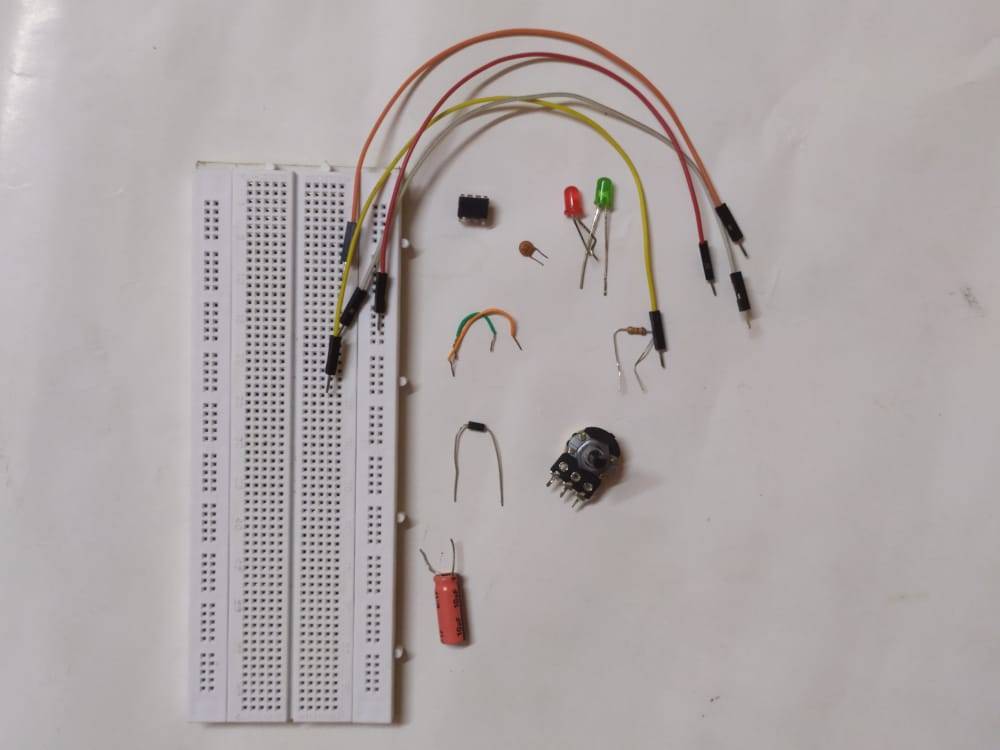
Components Required
| 555 Timer ic | |
| LED | BUY LINK |
| 1N4007 diode | BUY LINK |
| resistor 22k | BUY LINK |
| capacitors 0.01 uF, 10 uF | BUY LINK |
| 100K potentiometer | BUY LINK |
| 9 volt battery | BUY LINK |
| jumper wire | BUY LINK |
| Breadboard | BUY LINK |
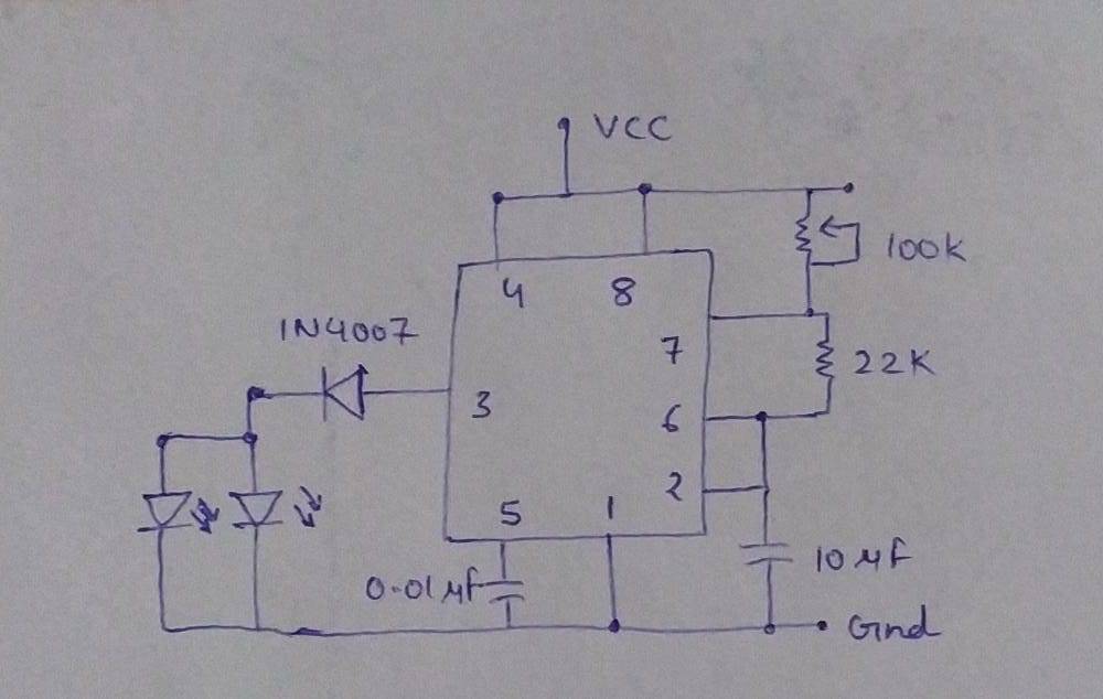
555 timer circuit Diagram for railway project
- Take a 555 timer ic and place it on the breadboard such that the notch is on the top so that it is easy for you to identify the pins.
- First of all, connect pin 1 with the negative terminal of the power supply and pin 8 with the positive terminal of the power supply.
- Join pins 2 and 6 together. Connect a 0.01 uF capacitor between pin 5 and the negative supply. Then take a 10 uF capacitor and connect its positive leg with pin 2 and the negative leg with the negative supply.
- Join pin 6 and 7 together via a 22K resistor. Connect pins 4 and 8 together. Place a 100K potentiometer as shown in the circuit diagram.
- Connect the positive leg of the diode with pin 3 and the negative with the first switch. To the other pins of the switch connect the positive leg of one LED.
- Do the same for the second LED and switch. Ground the negative legs of both the LEDs. Your circuit is complete now and ready for testing.
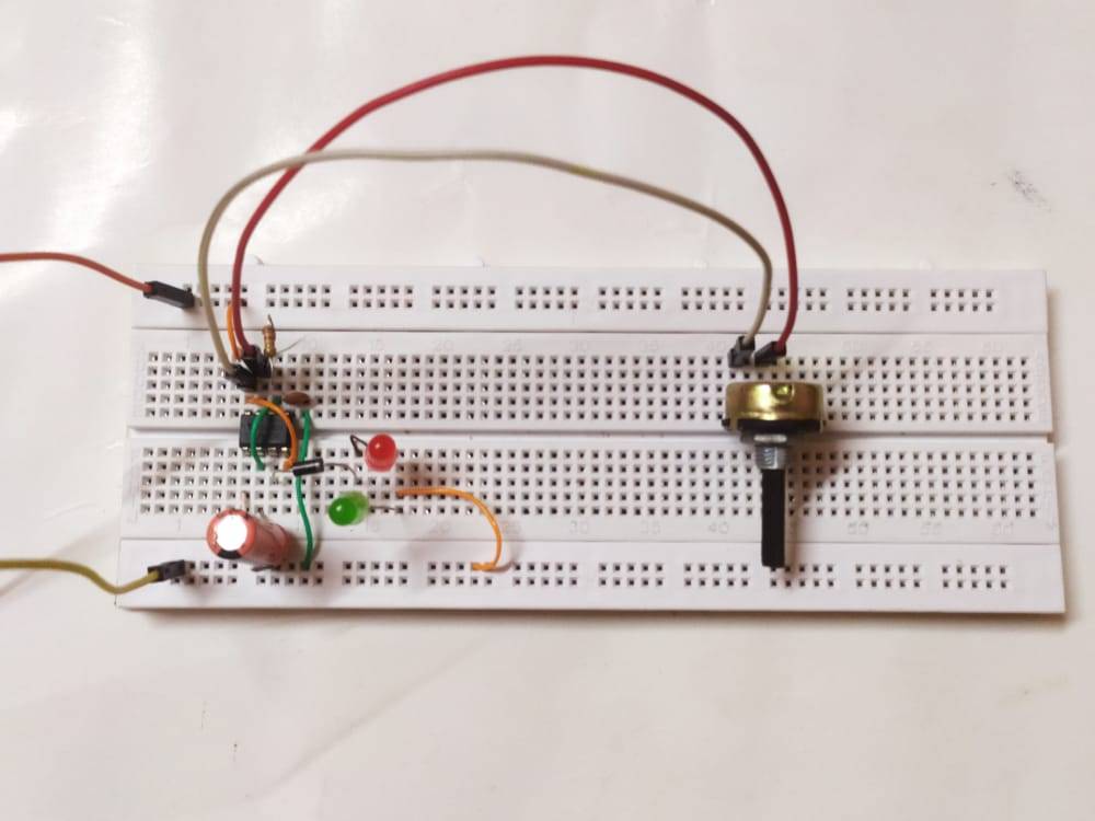
Let’s Test the Circuit
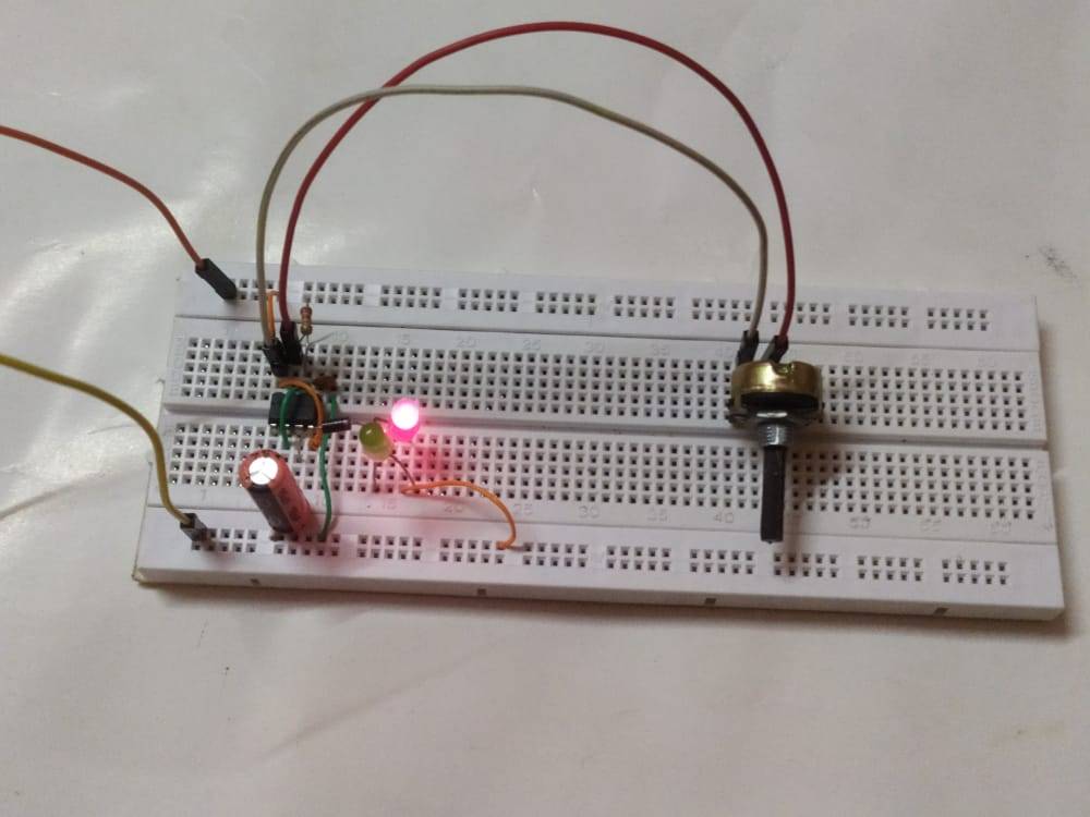
We hope that understand the railway signal circuit completely and now please try to make it on your own. If you have any doubts or suggestions regarding this post then do let us know in the comments section given below. Also, do check out more tutorials on Arduino and Raspberry Pi.
Related Projects
How to make 555 timer oscillator | NE 555 oscillator
how to make automatic street light Using 555 timer ?
Tea Coffee Vending Machine using 555 timer | 555 timer Project
Digital Dice Using 4017 IC And 555 IC | 555 Timer project
traffic light project Circuit Using 555 Timer IC | 555 IC Project
Thanks for reading.