
Hello Friends, After a long time I’m going to discuss an important and interesting article based on Raspberry Pi PICO. I assume that many of you might be familiar with Raspberry Pi PICO, if not then visit my Raspberry Pi Series articles from where you can start learning about it. Now let’s focus on our main topic i.e., Hall Effect Sensor PI PICO, IT is a rather simple but useful project. It consists of a simple module and a PI PICO to make a working circuit.
Table of Contents
Hall Effect Sensor

Hall Effect Sensor, as it’s name symbolizes, that it deals with the areas of magnetic field and flux. Magnetic field can either be generated by using a coil or from a natural magnet. The sensor is easily available in market also works with any microcontroller and within any condition pretty well. But to enhance it’s functioning, it is paired with an Op-Amp with amplifies the signal or output from the Linear Hall-Effect Sensor.
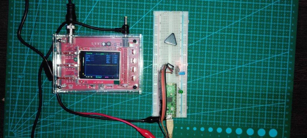
The module comes with a LM393 Op-Amp, also a 10K preset to adjust the sensitivity of the sensor. The module also has an on-board LED to indicate the detection of magnetic field the sensor is currently in. Although this sensor works for on and off, It gives both Digital & Analog data. I have attached its wave form in an oscilloscope down below.
Note: For detailed expiation of topics and understanding the circuit diagram, visit my respective articles anchored beside each keyword.
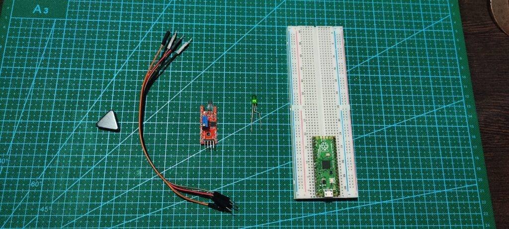
Material Required
|
S.No |
Component Required |
Quantity |
Buy Link |
|
1. |
Raspberry PI PICO |
1 | BUY LINK |
|
2. |
Hall Effect Sensor |
1 | BUY LINK |
|
3 |
LED |
1 | BUY LINK |
|
4. |
220 Ohm Resistor |
1 | BUY LINK |
|
5. |
Jumper Wire |
40 | BUY LINK |
|
6. |
Breadboard |
1 | BUY LINK |
|
7. |
Power supply |
1 | BUY LINK |
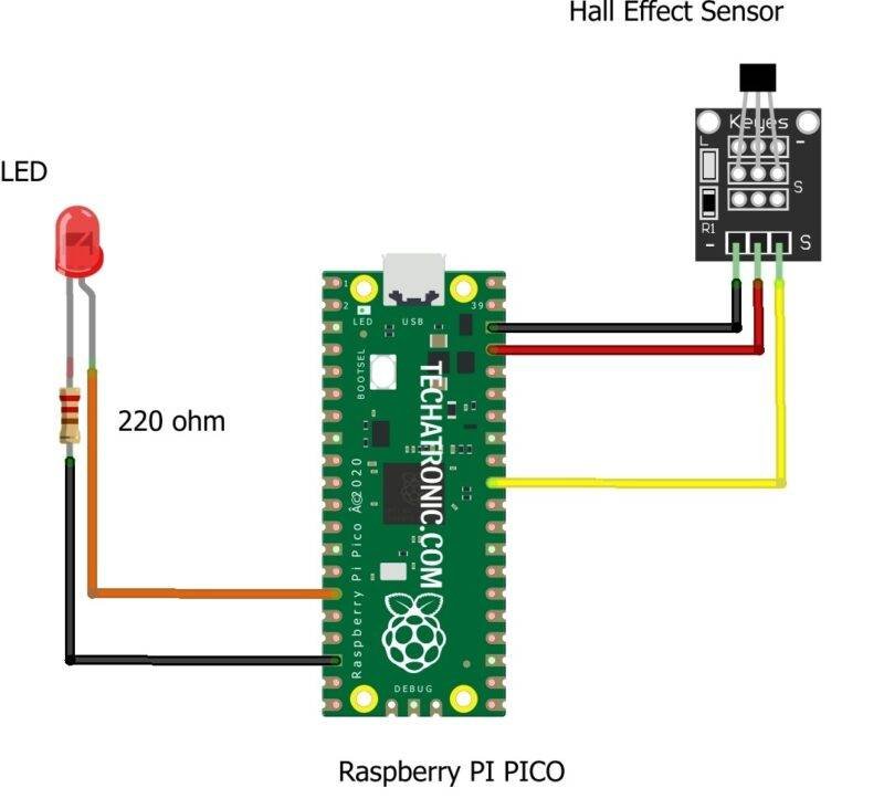
Circuit Diagram
|
Raspberry PI PICO |
Hall Effect Sensor | |
|
GPIO 26 Pin |
D0 | |
|
3.3V |
VCC | |
|
GND |
GND | |
|
Raspberry PI PICO |
LED |
220 ohm Resistor |
|
GPIO 11 Pin |
Anode Terminal ( + ) |
|
|
GND |
|
Terminal 1 |
|
|
Cathode Terminal ( – ) |
Terminal 2 |
Hall Effect Sensor D0 Pin to GPIO 26 & LED to GPIO 11 of Raspberry Pi PICO and power line to 3.3V(OUT)/VBUS and GND respectively
Code & Explanation
Explanation
In the first two lines we have imported some important modules which are required for the program to work i.e., machine module (Pin function) and time module for time related calculations.
Then in the next two lines we have defined two pins, one for Hall-Effect Sensor input and the other for Led which we have used to indicate detection of magnetic field. You can change these pins according to your needs but keep in mind to change the pin number according to the GPIO numbering of PICO.
After it in while loop, we put our main code in try and except format to make code terminate at Keyboard Interrupt. In while loop, we put if condition to check for the high input on Hall-Effect sensor and according to that we toggle Led high or low.
Code
 from machine import Pin
 import time,utime
 he=Pin(26,Pin.IN)
 led=Pin(11,Pin.OUT)
 while True:
   try:
     if he.value() == 0:
       led.value(0)
     elif he.value()==1:
       led.value(1)
   except KeyboardInterrupt:
     break