
Hello Guys, I’m back again with another interesting article on Basic Electronics. Today I’m going to open up the topic about Op-Amp. Operational amplifiers are a very important topic in basic electronics and are also needed in developing your own circuits. These types of IC’s are not only very easily available but also available in a variety of packages and types. So there is large scope in the field of Op-Amp usage. So let’s start today’s topic.
What is Op-Amp?
Op-Amp stands for Operational Amplifiers. As the name identifies that, it basically works as amplifiers. Yes, it’s true the very basic application of Op-Amps is amplification, but of what type it depends on the version used and its application in that circuits. Amplifiers can be used for amplifying signals & filtering. These are very useful for small-scale and less cost work, but for professionals, high quality and fewer distortion versions should be used.
Operational Amplifiers work according to the input given on its inverting and non-inverting input. For easiness, I say its + & – inputs. The symbol of an amplifier is like this, with + & – terminal as an input terminal for amplification and out terminal as amplified output.
This is all for the introduction of Op-Amp, now let’s see its working and applications.
Applications & Working:-
Non-Inverting Amplifier Circuit:
This is the first application of an Op-Amp. The basic design of this application is shown above. In this type of circuit, the output voltage remains in the positive region of the value. Also, gain (limit & times) are clearly identified in the datasheet of the specific Op-Amp. So read it carefully while using or choosing one.
G(gain) = 1+(R2/R1)
This is the basic formula for calculating the Number of times gain on the output side of an Op-Amp. Also, the Output voltage can be calculated by
Vout = G x Vin Here: Vin(+)=Inverting input(+), Vin(-)=Non-Inverting Input(-)
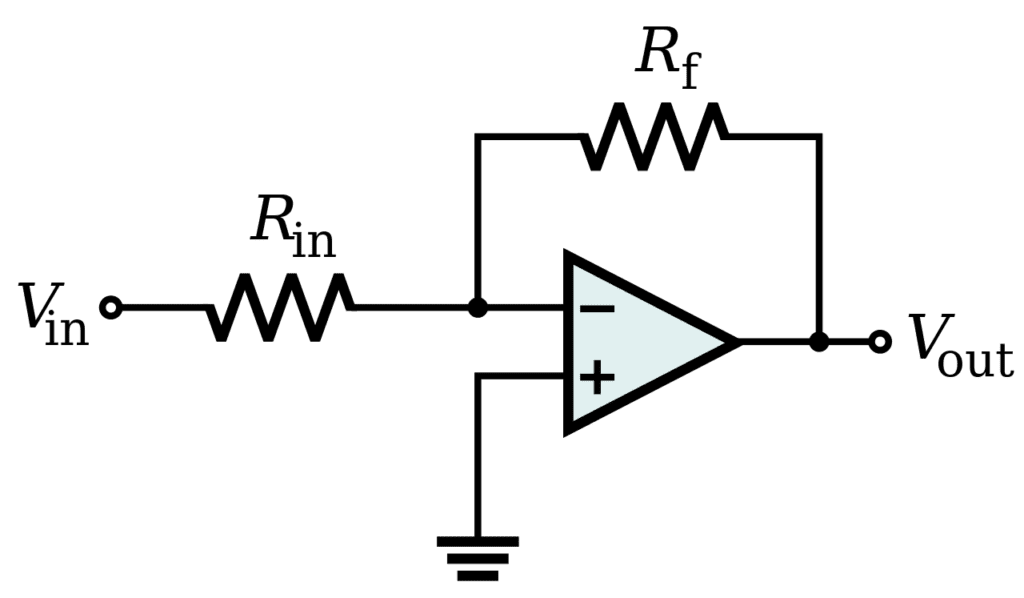
Inverting Amplifier Circuit:
In this type of application, the basic diagram is shown above. Also in this type, the output voltage is in negative value. This means as the input of inverting voltage increases, the output voltage becomes more in negative value. In short, you can say that it is inversely proportional to the inverting voltage. The only difference is that non-inverting input in this becomes Vin(+) and inverting input becomes Vin(-).
G(gain)=R2/R1
Vout = -G x Vin Here: Vin(+)=Non-Inverting input, Vin(-)=Inverting input
So with this end this basic tutorial on Op-Amp is mainly used for understanding the concept of Op-Amps. If you want more knowledge about this then comment below I’ll update the article as soon as possible.