
Hey geeks, welcome back to Techatronic. We are back with another new project in the series of 555 timer projects. So in this article, we are making this article how to make 555 timer oscillator circuit using ic 555.
Do you know what an oscillator is? If not then don’t worry read the full article and we are sure that you can make your own oscillator circuit.
Well, 555 timer ic can be used for making different projects especially when we are working on time delays. You can also read our articles on Arduino and IoT. So are excited about making it?
Table of Contents
Components Required

| 555 timer ic | |
| Resistors 1K, 75K | BUY LINK |
| Capacitor 0.01 uF, 1 uF | |
| Connecting wires | BUY LINK |
| breadboard | BUY LINK |
| 12Vvolts power supply | BUY LINK |
| 1N4148 diodes | BUY LINK |
Basic Square Wave 555 Oscillator Circuit
A 555 timer ic can be used to generate a square wave in its astable mode of operation. The generated square wave has a fixed frequency and if you want to make changes to it you have to increase and decrease the values of the resistors (1K and 75K) that we used in our circuit.
Connect a 5 or 9 volts dc power supply to the circuit and if you don’t have a CRO to check the output you can simply place a speaker at the output pins and listen to the ticking sound coming from it. You can also check the LED flasher light using 555 timer ic made by us.
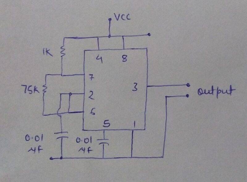
555 Oscillator Circuit diagram

- Take a 555 timer ic and connect pins 4 and 8 together.
- Connect pin 7 to the positive supply via a 1K resistor.
- Join pins 2 and 6 with each other. Connect a 75K resistor between pins 7 and 6.
- Take a 0.01 uF capacitor and connect its positive leg with pin 6 and negative leg with the negative supply.
- Join a 0.01 uF capacitor between pin 5 and the negative supply.
- Connect pin 1 of the ic with the negative supply.
- You can take the output from pin 3 and the negative supply.
Duty cycle of astable multivibrator
In this version, we just add two guiding diodes that are 1N4148 Zener diodes. These diodes help in channelizing the charging and discharging current to the timing capacitor.
Basically, the duty cycle is the ratio of the time a circuit is on compared to the time the circuit is off. You can also check the PWM dc motor speed controller circuit using 555 ic made by us.
Circuit Diagram for Oscillator Circuit
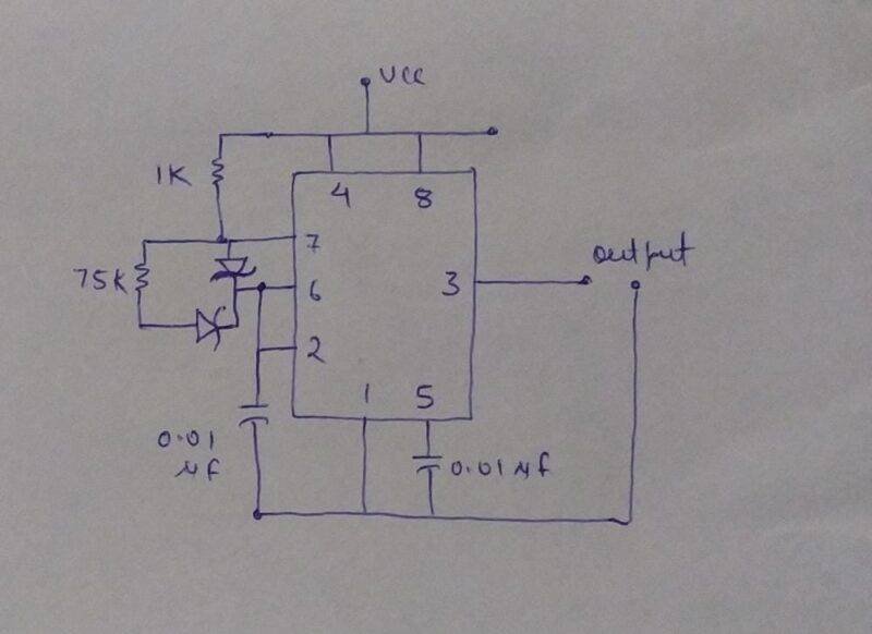
You just need to connect two diodes in the circuit that we made earlier in this project. Take two Zener diodes and connect the negative leg of one diode with pin 6 and the positive leg with pin 7. For the second diode connect the negative leg with a 75K resistor and the positive leg with pin 6. You can take the output from pin 3 of the 555 timer ic and the negative terminal of the power supply.
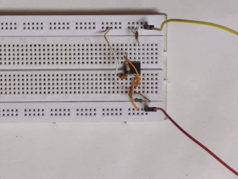
Let’s Test the Circuit
We hope that you understand the work and the concept used in this project. If you have any doubts regarding this project then tell us in the comments section given below. Also, do check out more tutorials on Arduino and Raspberry Pi.
Thanks for reading.