
Introduction
Hey geeks, welcome back to Techatronic. In this article, we are going to make a Light Sensor Circuit using a 555 Timer. The light sensor circuit will detect the dark and light around it. Now let us discuss the working of this circuit. You can also read more articles on Arduino and IoT published by us.
The circuit comprises a 555 clock designed in monostable mode, an LDR, a resistor, and a Drove. At the point when the LDR is presented to light, its obstruction diminishes, and the voltage at the trigger pin (pin 2) of the 555 clock dips under its edge voltage, setting off the result pin (pin 3) to go high. This turns on the Drove or can be utilized to set off a transfer.

Description
- This circuit is very helpful in case if you forgot to close the door of your refrigerator or the door is not closed properly.
- In this circuit, we are using an LDR with two 555 timer ic’s.
- When the light coming inside the refrigerator falls on the LDR then the buzzer starts ringing.
- The light of the refrigerator turns on only when you open the door otherwise it is off.
- So the buzzer only rings when the door is open.
- You can also check the electronic mosquito killer circuit made by us.
Components Required
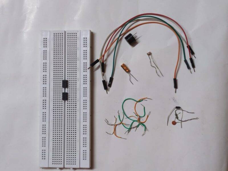
| Two 555 timer ic | |
| LDR Sensor | BUY LINK |
| Buzzer | BUY LINK |
| Resistors 10K, 1M | BUY LINK |
| Capacitors 1 uF, 100 nF | BUY LINK |
| 9 volts battery | BUY LINK |
| 1N4007 diode | BUY LINK |
| Connecting wires | BUY LINK |
| Breadboard | BUY LINK |
Light Sensor Circuit diagram using 555 Timer
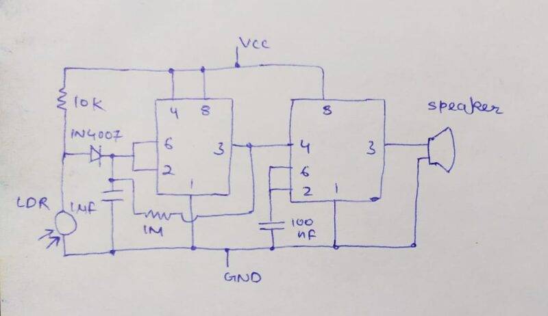
- Take a breadboard and place two 555 timer ic’s on it. Then connect pin 8 of both of the ic’s with the positive rail of the breadboard.
- Join pin 1 of the both of the ic’s with the negative rail of the breadboard.
- Now let us see the connections for the first 555 timer ic.
- Connect pin 3 with pin 4 of the second timer ic.
- Join pins 2 and 6 together. Take a diode and connect its positive leg with pin 6 and the positive leg with the positive rail of the breadboard via a 10K resistor.
- Attach a LDR between the positive leg of the diode and the negative rail.
- Connect a 1 uF capacitor with pin 2 and the negative rail as shown in the diagram.
- Join pins 3 and 2 using a 1M resistor.
- Now let us see the connections for the second 555 timer ic.
- Join pins 2 and 6 with each other. Connect a 100 nF capacitor with the negative rail and pin 2 of the ic.
- Take a buzzer and join its positive leg with pin 3 and the negative leg with the negative rail.
- Join pins 3 and 2 via a 1M resistor. Your circuit is now ready for testing.
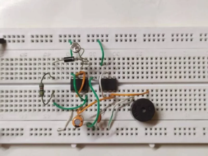
when you completed the circuit check once again the connections. it should be right at the same in circuit diagram given above and properly connected.
Let’s Test the Light detector Circuit
We hope that you liked the light detector circuit project and if you have any doubts regarding it then please feel free to tell us in the comments section given below. Also, do check out more tutorials on Arduino and Raspberry Pi.
Light detector circuit using LDR sensor combined with the 555 timers ic. and make this perfectly working circuit for your projects. it can replace the Light sensor using Arduino and many other controllers. where you need an expensive controller to make this circuit. this 555 timer light detector can be used at your home and many other places.
all the steps and other things which are necessary to make this project we have shared above.
Thanks for reading.