

Hey guys, hope you are doing fine. We are back with another new project in the series of 555 timer ic projects. We are sure that you know about what a vending machine is and how to use it. So in this article, we are going to make a simple tea coffee vending machine using a 555 timer ic.
A vending machine is useful as it reduces the human efforts in selling various things. We can select any item from the window display and buy it using the vending machines. You just have to select the items and put the money into the slot, It calculates the balance and drops the items into the basket.
All the details are given below with step by step circuit guide. You can also read more articles on Arduino and IoT published by us.
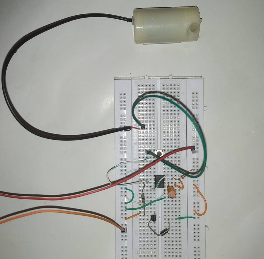
Table of Contents
About this Project
This is a tea coffee vending machine project that we made using 555 timer ic project. You can press the push button in order to get tea or coffee. When you press the button the pump is in action and starts filling your cup with the liquid.
There is a transistor in the circuit that is responsible for turning the pump on and off. You can fill the jar in which the pump is dipped with any liquid drink of your choice and this vending machine is for your personal use only as it didn’t ask you for the money. You can also check the LED fade in and out circuit using 555 ic made by us.
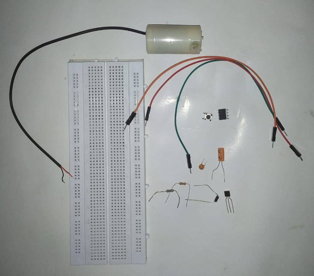
Components Required
| 555 timer ic | |
| Resistor 1k,100k,1k,10k | BUY LINK |
| 555 timer ic | |
| Diodes 1N4007, 1N4148 | BUY LINK |
| DC pump | BUY LINK |
| BC547 transistor | BUY LINK |
| Push-button | BUY LINK |
| Connecting wires | BUY LINK |
| Breadboard | BUY LINK |
Circuit for Tea Coffee Vending Machine

First of all, take a 555 timer ic and connect its pin 1 to the negative rail and pin 8 to the positive rail.
Join pin 4 with pin 8. Attach a 0.1 uF capacitor between pin 5 and negative rail.
Place a 1K resistor between pin 7 and positive rail. Join pins 7 and 6 together.
Now take a 100 uF capacitor and connect its positive leg with pin 6 and negative leg with the negative rail.
Join pin 2 with the positive rail via a 100K resistor.
Then take a push-button and connect pin 2 with one pair of interconnected pins.
Connect the positive leg of a Zener diode with another pair of interconnect pins of the push-button.
To the negative leg of the Zener diode connect a 1K resistor and then Connect it with the dc pump as shown above.
Connect the other wire of the dc pump with the negative rail. Now take a BC547 transistor and connect its base with pin 3 of the ic via a 10K resistor.
Join the emitter pin with the negative rail. Connect the collector pin with the positive leg of the 1N4007 diode. Attach the negative leg of the diode with the positive rail. Your circuit is now complete.
Let’s Test the 555 timer Circuit
We hope that you liked this project and understand the working of this project completely. If you have any doubts regarding this post then let us know in the comments section given below. Also, do check out more tutorials on Arduino and Raspberry Pi.
Thanks for reading.
Latest 555 timer projects
traffic light project Circuit Using 555 Timer IC | 555 IC Project
Astable Multivibrator using 555 timer | 555 timer square wave generator
555 delay timer with ON/OFF | 555 timer delay off circuit
LED Brightness Control using Potentiometer| LED Fade | 555 timer project
Cell Phone Signal Jammer Using 555 IC | 555 timer project signal jammer