
Hey geeks, welcome back to Techatronic. In this article, we are going to discuss different types of rectifier circuits. So before exploring the types let us first understand what is a rectifier circuit and where we use them. In your home mostly appliances need constant dc supply to work, like TV, audio systems, computers, etc.
Table of Contents
Introduction to Rectifier
They cant operate on the alternating current which is supplied directly in the switchboards of your home. so, here we are going to explain to you the function of the rectifier. The rectifier is one of the widely used electronic components which mostly use in each electronic device. In India 230 volts AC is generally supplied for domestic use. So without wasting any time let us discuss the construction and working of different types of rectifiers. here we will learn what is a rectifier. You can also read our articles on IoT and basic electronics.
The rectifier is a device that is used to convert the AC signal into the DC signal. in the AC signal, we will get two-phase one is positive and the other is negative. if your circuit doesn’t need the negative half cycle you can use a rectifier to remove that.

You can see in the above image and get to know why we use the rectifier circuit. So, there are three types of rectifiers half-wave rectifiers full-wave rectifiers and full-wave bridge rectifiers which we gonna explain below. so, read the full article.
Types of Rectifier
there are three types of rectifiers half-wave rectifier & full-wave rectifier. it depends on the application where you are using the rectifier. in a half-wave rectifier, only half cycle of AC signal rectifies by this rectifier. all the details about the half-wave rectifier have given below. full-wave rectifier and full-wave bridge rectifiers. how they differ from each other, advantage, disadvantage, etc. In a full-wave rectifier there are also two types one is a normal rectifier which needs the center tape rectifier and another which does not need the center tape transformer. it needs a simple transformer. which is known as the bridge rectifier.
Half-Wave Rectifier
Do you know what is a Diode is? Well if not then do check our article on it. A diode only conducts current in one direction only and this feature makes them ideal for rectification. We connect them together with each other to make a rectifier. A half-wave rectifier can only rectify the positive half cycle of the AC signal.
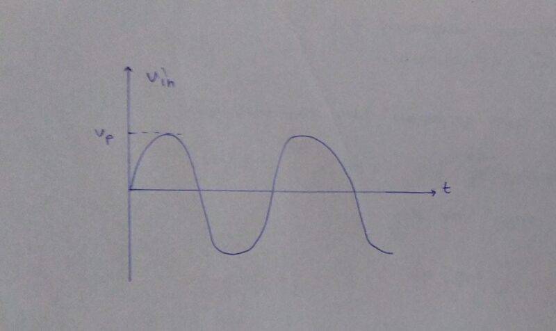
in ac signal, we get both phases positive as well as negative which can be seen in the sine wave. so, to get rid of the negative half cycle we use the rectifier. Talking about a half-wave rectifier, it is the simplest of all rectifier circuits.
Circuit for a Half-Wave Rectifier

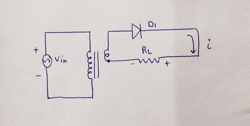
- During the positive half cycle of the source voltage, the diode is forward bias and it will conduct.
- In this case, the diode will act as a closed switch and we got a positive half cycle across the load resistor.

- But during the negative half cycle of the source voltage, the diode will reverse bias.
- In this case, the diode will act as an open switch and we got no voltage across the output.
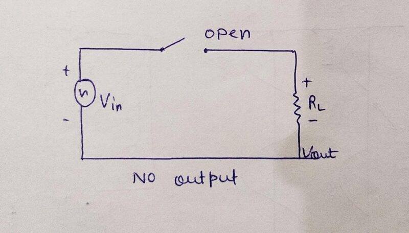
- So the diode will conduct only during the positive half cycle.
- The half-wave rectifier clips off the negative half cycles making the circuit unidirectional.
DC Value of a Half Wave Signal
- It is the same as of average value which can be calculated using Vdc= Vp/ Pi.
- From this equation, we can conclude that the DC value of a half-wave signal is about 31.8% of the peak value i.e if the peak value is 10 V then the DC voltage will be 3.18 V.

Output Frequency
The variations of the rectified output waveform produce a large number of ripples which has the same frequency as the input AC supply. Hence we can write Fout=Fin.
Limitations of Half-Wave Rectifier
- If the value of the load resistor is small for a given capacitor value, a high current will flow through the load which discharges the capacitor more quickly and ultimately results in increased ripples.
- We need a larger value capacitor to have a greater RC value time constant.
- As long as the RC time value constant is greater than the period, the capacitor remains fully charged and we get a perfect DC output voltage.
- This is not practical because of the limit on both the cost and size of a rectifier.
- Another major drawback of a half-wave rectifier is no output during the negative half cycle hence half of the power is wasted which results in lower output amplitude.
- Due to these drawbacks, half-wave rectifiers are rarely used.
- We prefer a full-wave rectifier over them. Read about the construction and working of a full-wave rectifier below.
Full-Wave Rectifier
It is the most used rectifier circuit in the power rectification field. Although the circuit is a bit more complex it offers some significant benefits over a half-wave rectifier. It can work on both cycles of the input AC supply and also the output has much fewer ripples which makes it easier to produce a smooth output waveform.
Circuit for a Full-Wave Rectifier
- There are two diodes in a full-wave rectifier so that both the input cycles can be rectified.
- It also uses a transformer with the center tapped secondary winding.
- You can also understand it as two half-wave rectifiers are connected together but the polarity of diodes is changed.

- During the positive half cycle of input AC supply, diode1 is forward bias and conducts, and diode2 is reversed bias so it didn’t conduct.
- There is an output voltage due to diode1 across the load.
- During the negative half cycle of input AC supply, diode1 is reversed bias and diode2 is forward bias.
- Only diode2 will conduct and there is an output voltage due to diode2 across the load.
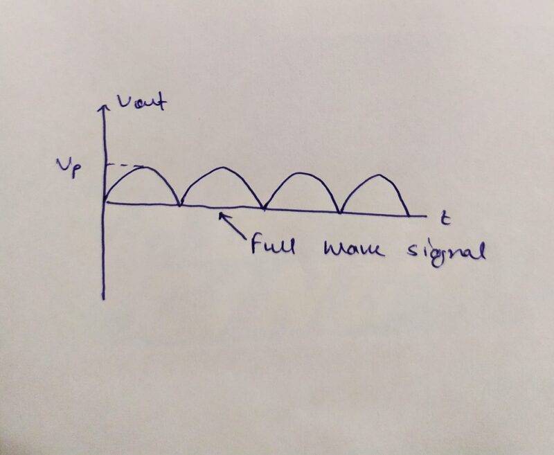
- As a result, the rectified load current flows during both half cycles due to which we get a full wave signal across the load.

Output Frequency
It inverts each negative half cycle, doubling the number of positive half cycles and because of it, full-wave output has twice as many cycles as the input. Hence the frequency of the full-wave signal is double the input frequency such that Fout=2Fin. If the line frequency is 60 Hz, the output frequency will be 120 Hz.
Limitations of Full-Wave Rectifier
- One of the major disadvantages of this type is the necessity of a transformer with center tapped secondary windings.
- These kinds of transformers are quite large in size and also very costly.
- Another drawback is that because of the center tap, only half of the secondary voltage is used for rectification.
Bridge Rectifier
There are two types of rectifiers. half-wave and the full-wave now the question is what is bridge rectifier is a special type of rectifier. it is a type of full-wave rectifier which have the simplest working and maximum efficiency. there is 4 r more diode connected as a bridge we are sharing some images of the bridge rectifier. it can convert the ac current to dc by using the diode concept. there is 4 diode connected in a manner that can give the maximum efficiency.
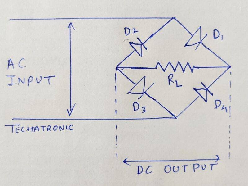
As you can see in the above image. there are 4 diode arranges in the bridge manner.
Bridge rectifier Construction
There is two input port in the rectifier that uses forgiven the input ac signal to the rectifier. now we have to attach two rectifiers to the one terminal of the ac input. one is forward biased and another is reversed biased. now you have to connect one load resistor with both ends of the diodes. now connect two diodes, in the same manner, one is reversed and another in forward with another terminal of the ac input. now there are two free terminals of the diodes which you have connected just now. connect these terminals to the load same load resistor. so, now as the load resistor, there are 4 diodes terminals. and you can get the output from the same point.
Bridge rectifier working
The Bridge rectifier working si very simple you just have to focus on the diode working. there is two-cycle of ac one is positive and the other is negative. in half cycle, the ac goes to the maximum in positive from zero which is known as the positive half cycle and same there the negative half cycle which goes to the highest peak in negative. as you can see in the sine wave.
Positive half cyle

so, when it’s positive half the one diode D1 is forward biased and the other diode D2 is reversed biased. so, only one diode will allow the current to pass., and from Current will return by the D3 diode which is in the forward biased condition. so it will too allow passing the current and it will complete the circuit. so, now you will get the first positive cycle in positive output.
Negative half cycle
As all, we know the diode is working in two ways one is reversed and one is forward. in the only forward biased condition it can allow passing the current. so we are using this logic here to make the bridge rectifier.

in this negative half cycle, the current will go from the other side. because the terminal polarity will change. in the first positive half cycle, the current passes through terminal 1 now the current will pass through terminal 2. now the diode D4 is in the forward biased, and D3 is revered biased. the diode D4 will allow passing the current. and you can get that at the load resistor. after the load resistor, the current passes through the diode D2 and returns to the sources.
in this way you can get both the cycle in positive, there will be no more negative cycle. so, now you can say it is the DC current. which you can see in the given image.
Output of Bridge rectifier
Uses of Bridge rectifier
- you can use this bridge rectifers into moculating the radio signals where it can detect the amplitude of the radio signals.
- bridge rectifier can be use into the welding machines.
- due to the efficient nature of the bridge rectifier, it use into many electronic apliance like power adaptor , tv, fridge , etc.
- the brifge rectifer can be where we need to rectify the high AC source.
- For the powering up of the devices it may be LED or DC motor this type of rectifiers are preferably used.
Applications of a Rectifier
- So a rectifier is a device that converts this incoming AC voltage into constant DC voltage at the output.
- Now a question may come to your mind like we convert AC voltage to DC voltage so can we convert DC voltage into AC voltage too?
- Well yes, we can convert it back. The device which is used for this purpose is known as an inverter.
- In your homes, you may have an inverter with one or two batteries that automatically goes on when the main power is switched down or if there is a power cut in your area.
- The inverter has its batteries connected with it which provides DC power and the inverter converts this power into AC so that it can be used by the AC appliances at your home.
- there are many electronic item which required a contact dc current like mobile charger, tv, home speaker system, and much more. we can use some capacitors to reduce the ripple factor and use it at the maximum capacity and minimum flactuation.
FAQ
Q1. What is ripple voltage?
The amount of AC content present in the output DC causes periodic pulsating of the dc voltage which is derived from the AC source.
Q2. What is the TUF of a half-wave rectifier?
TUF of a half-wave rectifier is 0.2865
Q3. What is Peak Factor?
The ratio of maximum value to the RMS value.
Q4. What is the maximum efficiency of a Half and Full wave rectifier?
For a half-wave rectifier, the efficiency is 40.6% and for a full-wave rectifier, the efficiency is 81.2%.
Q5. What is form factor?
It is defined as the ratio of the RMS value to the average value.
Conclusion
We hope that you liked this article on types of rectifiers. If you have any doubts regarding any concept then feel free to use the comments section given below. Also, do check out our articles on Arduino and Raspberry Pi published by us.
Thanks for reading!