
Introduction
Hey guys, welcome back to Techatronic. In this article, we are going to discuss that how you can make your own RFID project sliding door lock using Arduino.
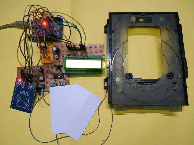
The messages will display on the 16×2 LCD screen. For controlling the movement of the motorized gate we are using an L298n motor driver module. You have to make the circuit first and then upload the given code to the Arduino. You can also check out more projects on Arduino and IoT.
Description
- This system is useful for making the home or office security projects.
- You are provided with smart cards to get access to the entrance.
- You have to put the smart card on the reader module.
- The system will automatically check for the correct card id and open the gate if the card id is matched with the data that we have provided earlier to the system.
- If the id of the smart card matched with the id present in the database then the green LED will glow else the red LED will glow along with the ringing buzzer.
- You can also check the windows login using RFID made by us.


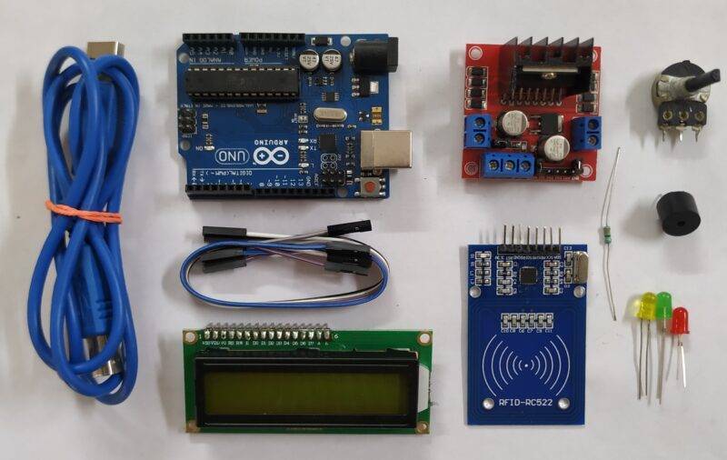
Components Required
| Arduino UNO | BUY LINK |
| RC522 RFID module | BUY LINK |
| 16×2 LCD | BUY LINK |
| 10K Potentiometer | BUY LINK |
| ON OFF switch | BUY LINK |
| L298n motor driver module | BUY LINK |
| 220 ohm resistors | BUY LINK |
| Jumper wires | BUY LINK |
| breadboard | BUY LINK |
| Buzzer | BUY LINK |
| LEDs | BUY LINK |
Circuit for RFID rfid project Sliding Door Lock

| Arduino UNO | RFID – RC522 Module | ||
| 10 Pin | SDA Pin | ||
| 13 Pin | SCK Pin | ||
| 11 Pin | MOSI Pin | ||
| 12 Pin | MISO Pin | ||
| No Pin | IRQ Pin | ||
| GND | GND | ||
| 9 Pin | RST Pin | ||
| 3.3 V | 3.3 V | ||
| Arduino UNO | Buzzer | ||
| 6 Pin | Positive | ||
| GND | Negative | ||
| L293D Module | Motor | ||
| Terminal 1 | Terminal 1 | ||
| Terminal 2 | Terminal 2 | ||
| Arduino UNO | 16*2 LCD | 10K Potentiometer | |
| GND | VSS, K | ||
| +5 V | VDD, A | ||
| GND | VSS (Ground) | Terminal 1 | |
| VEE ( Contrast ) | Terminal 2 | ||
| +5 V | VDD ( +5V ) | Terminal 3 | |
| A0 Pin | RS ( Register Select ) | ||
| GND | RW ( Read\Write ) | ||
| A1 Pin | E ( Enable ) | ||
| A2 Pin | D4 | ||
| A3 Pin | D5 | ||
| A4 Pin | D6 | ||
| A5 Pin | D7 | ||
| Arduino UNO | L298N Motor Module | Switch | Battery |
| 2 Pin | IN 1 | ||
| 3 Pin | IN 2 | ||
| 12 V | Terminal 1 | ||
| Terminal 2 | Positive | ||
| GND | GND | Negative | |
| 5 V | 5 V | ||
| Arduino UNO | LED 1 | LED 2 | 220 Ohm Resistor |
| 5 Pin | Anode Terminal | ||
| 7 Pin | Anode Terminal | ||
| GND | Terminal 1 | ||
| Cathode Terminal | Cathode Terminal | Terminal 2 |
First of all, let us see the connections between the Arduino and RFID modules.
- digital 10 pin -> SDA pin
- digital 13 pin -> SCK pin
- digital 11 pin -> MOSI pin
- digital 12 pin -> MISO pin
- GND pin -> GND pin
- 3.3v pin -> 3.3v pin
- digital 9 pin -> RST pin
- Now connect the Arduino analog pins with the 16×2 LCD using a 10K potentiometer as shown in the circuit.
- Join the positive leg of the red LED with the digital-7 pin of the Arduino.
- Connect the positive leg of the green LED with the digital-5 pin of the Arduino.
- Attach the negative legs of both of the LEDs to the GND pin via a 220 ohms resistor.
- Take a buzzer and connect its positive leg with digital-6 pin of the Arduino and the negative leg with the GND pin of the Arduino.
- Now connect digital-3 and digital-2 pins of the Arduino with the pins of the L298n motor driver.
- Connect a dc motor to one pair of side pins of the driver module.
- At last connect the terminals of the battery with the driver module and Arduino as shown above.

Code for RFID Sliding Door Lock
NOTE: Please upload the code given below to the Arduino. Before uploading you have to install <SPI.h>, <MFRC522.h>, and <LiquidCrystal.h> libraries to the Arduino IDE. Check here how to install zip libraries to the Arduino.
// TECHATRONIC.COM
// SPI Library
// https://github.com/PaulStoffregen/SPI
// MFRC522 Library
// https://github.com/miguelbalboa/rfid
#include <SPI.h>
#include <MFRC522.h>
#include "LiquidCrystal.h"
LiquidCrystal lcd (A0, A1, A2, A3, A4, A5);
#define SS_PIN 10
#define RST_PIN 9
#define LED_G 5 //define green LED pin D5
#define LED_R 7 //define red LED pin D7
#define BUZZER 6 //buzzer pin D+6
MFRC522 mfrc522(SS_PIN, RST_PIN); // Create MFRC522 instance.
void setup()
{
Serial.begin(9600); // Initiate a serial communication
SPI.begin(); // Initiate SPI bus
lcd.begin(16,2);
mfrc522.PCD_Init(); // Initiate MFRC522
pinMode(LED_G, OUTPUT);
pinMode(LED_R, OUTPUT);
pinMode(BUZZER, OUTPUT);
noTone(BUZZER);
pinMode(3, OUTPUT); // Motor pin
pinMode(2, OUTPUT); // Motor pin
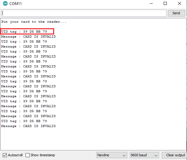
Serial.println("Put your card to the reader...");
Serial.println();
lcd.setCursor(0,0);
lcd.print(" Put your card ");
}
void loop()
{
// Look for new cards
if ( ! mfrc522.PICC_IsNewCardPresent())
{
return;
}
// Select one of the cards
if ( ! mfrc522.PICC_ReadCardSerial())
{
return;
}
//Show UID on serial monitor
Serial.print("UID tag :");
String content= "";
byte letter;
for (byte i = 0; i < mfrc522.uid.size; i++)
{
Serial.print(mfrc522.uid.uidByte[i] < 0x10 ? " 0" : " ");
Serial.print(mfrc522.uid.uidByte[i], HEX);
content.concat(String(mfrc522.uid.uidByte[i] < 0x10 ? " 0" : " "));
content.concat(String(mfrc522.uid.uidByte[i], HEX));
}
Serial.println();
Serial.print("Message : ");
content.toUpperCase();
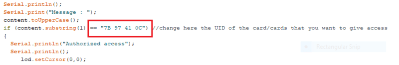
if (content.substring(1) == "7B 97 41 0C") //change here the UID of the card/cards that you want to give access
{
Serial.println("Authorized access");
Serial.println();
lcd.setCursor(0,0);
lcd.print(" CARD IS VALID ");
lcd.setCursor(0,1);
lcd.print("Opening the Door ");
digitalWrite(LED_G, HIGH); //Green LED ON
digitalWrite(LED_R, LOW); // Red LED OFF
digitalWrite(3, HIGH); // Motor Clock Wise Clock Direction
digitalWrite(2, LOW); // Motor Clock Wise Clock Direction
delay(2000);
lcd.setCursor(0,1);
lcd.print("closing the Door ");
digitalWrite(LED_G, LOW); //Green LED OFF
digitalWrite(LED_R, HIGH); // Red LED ON
digitalWrite(6, LOW); // Motor Anti Clock Wise Direction
digitalWrite(7, HIGH); // Motor Anti Clock Wise Direction
delay(2000);
digitalWrite(6, LOW); // Motor Stop
digitalWrite(7, LOW); // Motor Stop
lcd.setCursor(0,0);
lcd.print(" Put your card ");
lcd.setCursor(0,1);
lcd.print(" ");
}
else
{
Serial.println("CARD IS INVALID");
lcd.setCursor(0,1);
lcd.print("CARD IS INVALID ");
digitalWrite(LED_G, LOW); //Green LED OFF
digitalWrite(LED_R, HIGH); // Red LED ON
tone(BUZZER, 300); // Buzzer ON
delay(1000);
digitalWrite(LED_R, HIGH); // Red LED ON
noTone(BUZZER); // Buzzer OFF
lcd.setCursor(0,1);
lcd.print(" ");
}
}
We hope that you liked this project and if you have any suggestions or doubts regarding this project then ping us in the comments section given below. Also, do check out more articles on Arduino and Raspberry Pi.
Thanks for reading.