

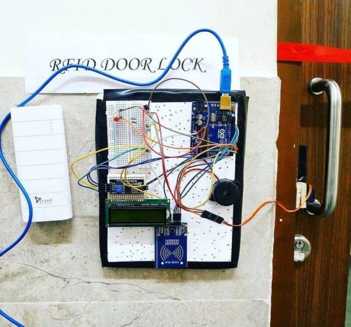
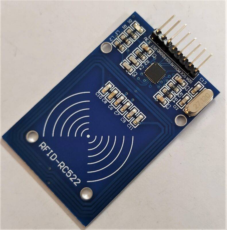
Hey guys, welcome back to Techatronic. In this article, we are going to discuss a very interesting project with Arduino. Have you ever seen a smart lock in which you have to put the card on the reader to get access? Well, we will make our own smart lock, an RFID lock system that needs a unique card to perform a specific action. We are using an RC522 RFID reader/writer module and an Arduino UNO board for making this smart lock. You can view the card status on a 16×2 LCD that we used here. Do check out more interesting projects on Arduino and Raspberry Pi made by us.
Working of the Project
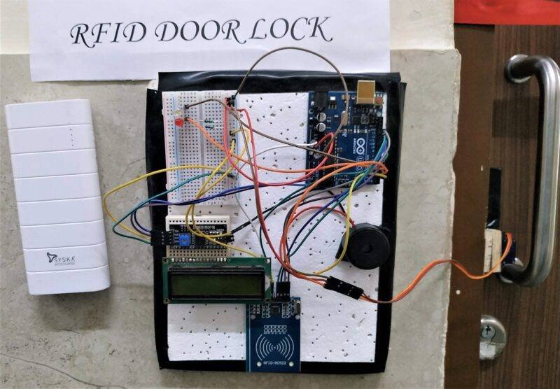
The RFID lock system works as when you will put the correct card to open the servo lock then “card is valid” this message will display and the green LED will turn on. The door will close automatically after a delay of three seconds, you can adjust this time in the code. For the invalid card the red LED will turn on with the message “card is invalid” and the buzzer starts beeping. The servo motor will rotate to open or close the gate. When you put an RFID card on the reader module then open the serial monitor to view the tag id of that card as shown below.
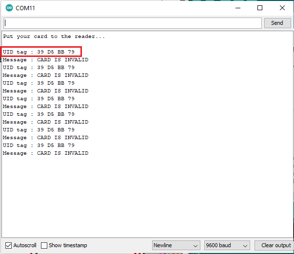
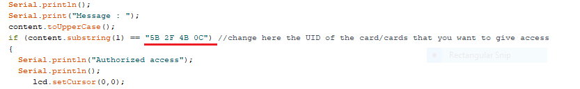
Add the tag id of the card that you want to use to open the lock in this section of the code.
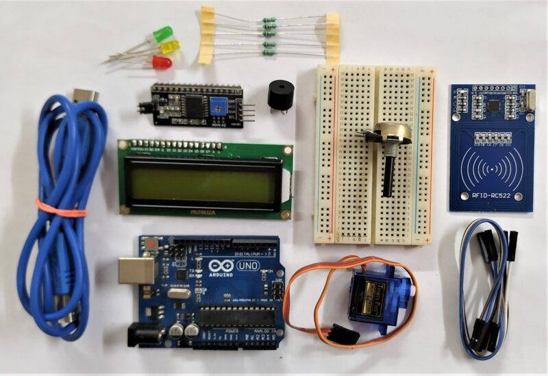
Components Required
| Arduino UNO | BUY LINK |
| 16×2 LCD | BUY LINK |
| I2C module | BUY LINK |
| Servo motor | BUY LINK |
| Buzzer | BUY LINK |
| Green and red LED | BUY LINK |
| Jumper wires | BUY LINK |
| breadboard | BUY LINK |
| RC522 RFID module | BUY LINK |
| 220-ohm resistors | BUY LINK |
| 10K potentiometer | BUY LINK |
| USB cable for uploading the code | BUY LINK |
You can buy all components together-BUY LINK
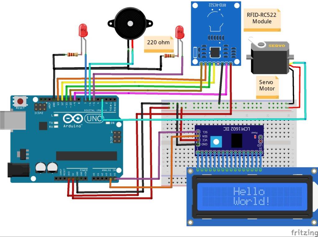
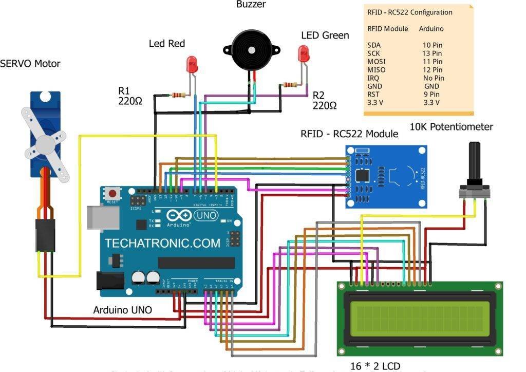
Arduino RFID Lock Circuit Diagram
With I2C module
If you are using the I2C module then find the address of the module first.
| Arduino UNO | RFID – RC522 Module | ||
| 10 Pin | SDA Pin | ||
| 13 Pin | SCK Pin | ||
| 11 Pin | MOSI Pin | ||
| 12 Pin | MISO Pin | ||
| No Pin | IRQ Pin | ||
| GND | GND | ||
| 9 Pin | RST Pin | ||
| 3.3 V | 3.3 V | ||
| Arduino UNO | Servo Motor | ||
| D3 Pin | OUT Pin ( Orange Colour ) | ||
| ( +5V ) | VCC ( Red Colour ) | ||
| GND | GND ( Black Colour ) | ||
| Arduino UNO | I2C LCD Module | ||
| ( +5V ) | ( +5V ) | ||
| GND | GND | ||
| A4 Pin | SDA Pin | ||
| A5 Pin | SCL Pin | ||
| 16 * 2 LCD | I2C LCD Module | ||
| 16 Pin Connect | 16 Pin Connect | ||
| Arduino UNO | Buzzer | ||
| D6 Pin | Positive | ||
| GND | Negative | ||
| Arduino | LED R | LED G | 220 Ohm Resistor |
| D7 Pin | Anode Pin | ||
| D5 Pin | Anode Pin | ||
| GND | Terminal 1 | ||
| Cathode Pin | Cathode Pin | Terminal 2 |
You can take a reference from one of our articles on I2C with LCD.
Arduino GND pin -> RFID GND pin, I2C GND pin, Servo negative wire, buzzer negative leg, LEDs negative leg via 220-ohm resistor
Arduino 5 volts -> I2C VCC pin, Servo positive wire
RFID 3.3 volts -> Arduino 3.3 volts
RFID RST pin -> digital-9 pin
RFID MISO pin -> digital-12 pin
RFID MOSI pin -> digital-11 pin
RFID SCK pin -> digital-13 pin
RFID SDA pin -> digital-10 pin
Green LED positive leg -> digital-5 pin
Red LED positive leg -> digital-7 pin
Buzzer positive leg -> digital-6 pin
Without I2C module
| Arduino UNO | RFID – RC522 Module | ||
| 10 Pin | SDA Pin | ||
| 13 Pin | SCK Pin | ||
| 11 Pin | MOSI Pin | ||
| 12 Pin | MISO Pin | ||
| No Pin | IRQ Pin | ||
| GND | GND | ||
| 9 Pin | RST Pin | ||
| 3.3 V | 3.3 V | ||
| Arduino UNO | Servo Motor | ||
| D3 Pin | OUT Pin ( Orange Colour ) | ||
| ( +5V ) | VCC ( Red Colour ) | ||
| GND | GND ( Black Colour ) | ||
| Arduino UNO | Buzzer | ||
| D6 Pin | Positive | ||
| GND | Negative | ||
| Arduino UNO | 16*2 LCD | 10K Potentiometer | |
| GND | VSS, K | ||
| +5 V | VDD, A | ||
| GND | VSS (Ground) | Terminal 1 | |
| VEE ( Contrast ) | Terminal 2 | ||
| +5 V | VDD ( +5V ) | Terminal 3 | |
| A0 Pin | RS ( Register Select ) | ||
| GND | RW ( Read\Write ) | ||
| A1 Pin | E ( Enable ) | ||
| A2 Pin | D4 | ||
| A3 Pin | D5 | ||
| A4 Pin | D6 | ||
| A5 Pin | D7 | ||
| Arduino | LED R | LED G | 220 Ohm Resistor |
| D7 Pin | Anode Pin | ||
| D5 Pin | Anode Pin | ||
| GND | Terminal 1 | ||
| Cathode Pin | Cathode Pin | Terminal 2 |
All the connections are the same except the I2C module. Connect the LCD pins with the analog pins of the Arduino as shown in the diagram. You can take help from our article on the working of LCD with Arduino.
Arduino Rfid Lock Code
NOTE: Please upload the given code according to the circuit you have made. Install <SPI.h>, <MFRC522.h>, <LiquidCrystal_I2C.h>, <Wire.h> libraries to the IDE first and then compile the code. Check here to know how to install a zip library to the Arduino IDE.
With I2C module
 // TECHATRONIC.COM
 // SPI Library
 // https://github.com/PaulStoffregen/SPI
 // MFRC522 Library
 // https://github.com/miguelbalboa/rfid
 #include <SPI.h>
 #include <MFRC522.h>
 #include <Servo.h>
 #include <Wire.h>
 #include <LiquidCrystal_I2C.h>
 LiquidCrystal_I2C lcd(0x3F,16,2);
 Servo s1;
 #define SS_PIN 10
 #define RST_PIN 9
 #define LED_G 5  //define green LED pin
 #define LED_R 7  //define red LED
 #define BUZZER 6 //buzzer pin
 MFRC522 mfrc522(SS_PIN, RST_PIN);  // Create MFRC522 instance.
 //Servo myServo; //define servo name
 void setup()
 {
  Serial.begin(9600);  // Initiate a serial communication
  SPI.begin();     // Initiate SPI bus
   lcd.init();
  lcd.backlight();
 ;
  mfrc522.PCD_Init();  // Initiate MFRC522
  s1.attach(3); //servo pin
  // myServo.write(0); //servo start position
  pinMode(LED_G, OUTPUT);
  pinMode(LED_R, OUTPUT);
  pinMode(BUZZER, OUTPUT);
  noTone(BUZZER);
  Serial.println("Put your card to the reader...");
  Serial.println();
  lcd.setCursor(0,0);
  lcd.print(" Put your card   ");
 }
 void loop()
 {
  // Look for new cards
  if ( ! mfrc522.PICC_IsNewCardPresent())
  {
   return;
  }
  // Select one of the cards
  if ( ! mfrc522.PICC_ReadCardSerial())
  {
   return;
  }
  //Show UID on serial monitor
  Serial.print("UID tag :");
  String content= "";
  byte letter;
  for (byte i = 0; i < mfrc522.uid.size; i++)
  {
    Serial.print(mfrc522.uid.uidByte[i] < 0x10 ? " 0" : " ");
    Serial.print(mfrc522.uid.uidByte[i], HEX);
    content.concat(String(mfrc522.uid.uidByte[i] < 0x10 ? " 0" : " "));
    content.concat(String(mfrc522.uid.uidByte[i], HEX));
  }
  Serial.println();
  Serial.print("Message : ");
  content.toUpperCase();
  if (content.substring(1) == "5B 2F 4B 0C") //change here the UID of the card/cards that you want to give access
  {
   Serial.println("Authorized access");
   Serial.println();
     lcd.setCursor(0,0);
     lcd.print(" CARD IS VALID      ");
     lcd.setCursor(0,1);
     lcd.print("Opening the Door   ");
     digitalWrite(LED_G, HIGH); //Green LED ON
     s1.write(0);
     delay(3000);
     s1.write(90);
     lcd.setCursor(0,1);
     lcd.print("closing the Door   ");
     digitalWrite(LED_G, LOW);  //Green LED OFF
     delay(2000);
     lcd.setCursor(0,0);
     lcd.print(" Put your card   ");
     lcd.setCursor(0,1);
     lcd.print("              ");
  }
  else
  {
   Serial.println("CARD IS INVALID");
    lcd.setCursor(0,1);
    lcd.print("CARD IS INVALID   ");
    digitalWrite(LED_R, HIGH);   // Red LED ON
    tone(BUZZER, 300);       // Buzzer ON
    delay(2000);
    digitalWrite(LED_R, LOW);
    noTone(BUZZER);
    lcd.setCursor(0,1);
    lcd.print("              ");
  }
 }
Without I2C module
 // TECHATRONIC.COM
 // SPI Library
 // https://github.com/PaulStoffregen/SPI
 // MFRC522 Library
 // https://github.com/miguelbalboa/rfid
 #include <SPI.h>
 #include <MFRC522.h>
 #include <Servo.h>
 #include <Wire.h>
 #include "LiquidCrystal.h"
 LiquidCrystal lcd(A0, A1, A2, A3, A4, A5);
 Servo s1;
 #define SS_PIN 10
 #define RST_PIN 9
 #define LED_G 5  //define green LED pin
 #define LED_R 7  //define red LED
 #define BUZZER 6 //buzzer pin
 MFRC522 mfrc522(SS_PIN, RST_PIN);  // Create MFRC522 instance.
 //Servo myServo; //define servo name
 void setup()
 {
  Serial.begin(9600);  // Initiate a serial communication
  SPI.begin();     // Initiate SPI bus
  lcd.begin(16,2);
  mfrc522.PCD_Init();  // Initiate MFRC522
  s1.attach(3); //servo pin
  // myServo.write(0); //servo start position
  pinMode(LED_G, OUTPUT);
  pinMode(LED_R, OUTPUT);
  pinMode(BUZZER, OUTPUT);
  noTone(BUZZER);
  Serial.println("Put your card to the reader...");
  Serial.println();
  lcd.setCursor(0,0);
  lcd.print(" Put your card   ");
 }
 void loop()
 {
  // Look for new cards
  if ( ! mfrc522.PICC_IsNewCardPresent())
  {
   return;
  }
  // Select one of the cards
  if ( ! mfrc522.PICC_ReadCardSerial())
  {
   return;
  }
  //Show UID on serial monitor
  Serial.print("UID tag :");
  String content= "";
  byte letter;
  for (byte i = 0; i < mfrc522.uid.size; i++)
  {
    Serial.print(mfrc522.uid.uidByte[i] < 0x10 ? " 0" : " ");
    Serial.print(mfrc522.uid.uidByte[i], HEX);
    content.concat(String(mfrc522.uid.uidByte[i] < 0x10 ? " 0" : " "));
    content.concat(String(mfrc522.uid.uidByte[i], HEX));
  }
  Serial.println();
  Serial.print("Message : ");
  content.toUpperCase();
  if (content.substring(1) == "5B 2F 4B 0C") //change here the UID of the card/cards that you want to give access
  {
   Serial.println("Authorized access");
   Serial.println();
     lcd.setCursor(0,0);
     lcd.print(" CARD IS VALID      ");
     lcd.setCursor(0,1);
     lcd.print("Opening the Door   ");
     digitalWrite(LED_G, HIGH); //Green LED ON
     s1.write(0);
     delay(3000);
     s1.write(90);
     lcd.setCursor(0,1);
     lcd.print("closing the Door   ");
     digitalWrite(LED_G, LOW);  //Green LED OFF
     delay(2000);
     lcd.setCursor(0,0);
     lcd.print(" Put your card   ");
     lcd.setCursor(0,1);
     lcd.print("              ");
  }
  else
  {
   Serial.println("CARD IS INVALID");
    lcd.setCursor(0,1);
    lcd.print("CARD IS INVALID   ");
    digitalWrite(LED_R, HIGH);   // Red LED ON
    tone(BUZZER, 300);       // Buzzer ON
    delay(2000);
    digitalWrite(LED_R, LOW);
    noTone(BUZZER);
    lcd.setCursor(0,1);
    lcd.print("              ");
  }
 }
Please share your views and suggestions regarding this project. If you have any doubts then feel free to use the comments section below.
HAPPY LEARNING!