
Hey guys, hope you are doing fine. In this article, we are going to make a digital counter using Arduino UNO and push buttons. For displaying the count we are using a 16×2 LCD. Are you familiar with the working of a push button with Arduino? If not then check our article on it. You can make more such amazing projects on Arduino. The EEPROM library helps us to read and write stored bytes. EEPROM is electrically erasable programmable read-only memory. Make the connections according to the given diagram and then upload the given code to the Arduino.

How Does Digital Counter Work?
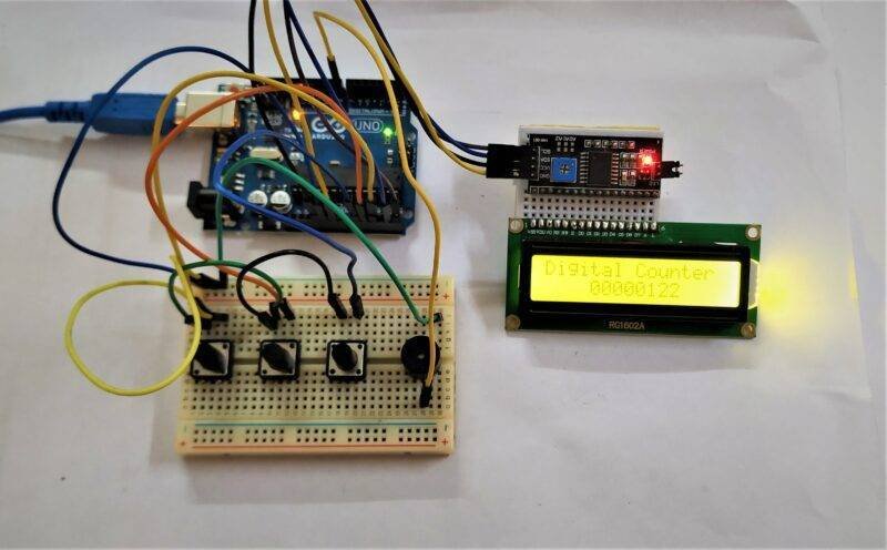
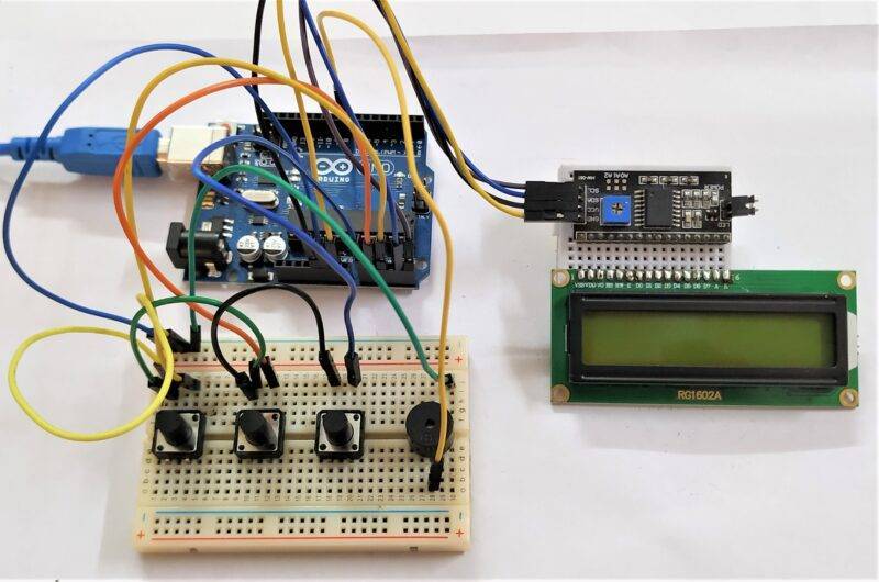
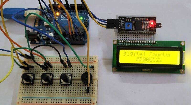
This project can increment the count by one when you press the UP push button and decrement the count by one when you press the DOWN push button. The count is displayed on a 16×2 LCD display. You can reset the count to 0 by pressing the RESET push button for a few seconds. On the LCD the count became 0. There is a buzzer in the project which beeps whenever you press a button. The whole circuit is fabricated on a breadboard. The best thing about this project is that it holds the value of the count so when the power is disconnected you will not lose your data. This is possible because Arduino has EEPROM, a memory whose values are kept when the board is turned off.
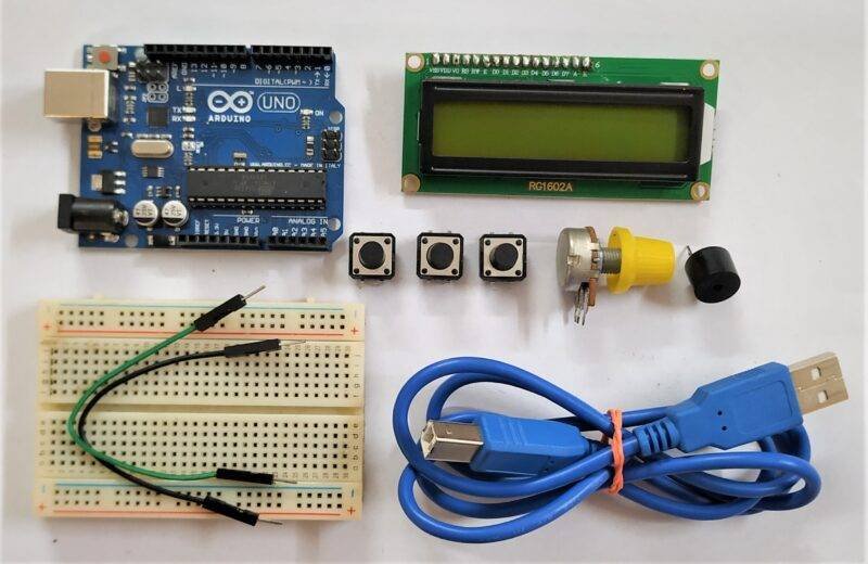
Components Required
- Arduino UNO
- 16×2 LCD
- Buzzer
- 10K-ohm potentiometer
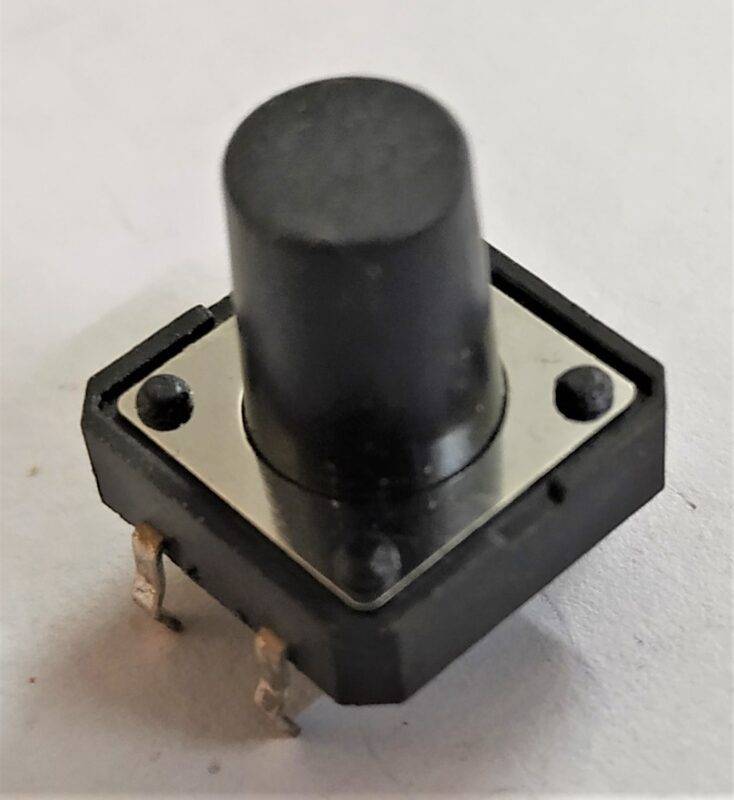
- Three push buttons
- Jumper wires
- Breadboard
- USB cable for uploading the code
- A Switch and a 9-volts battery
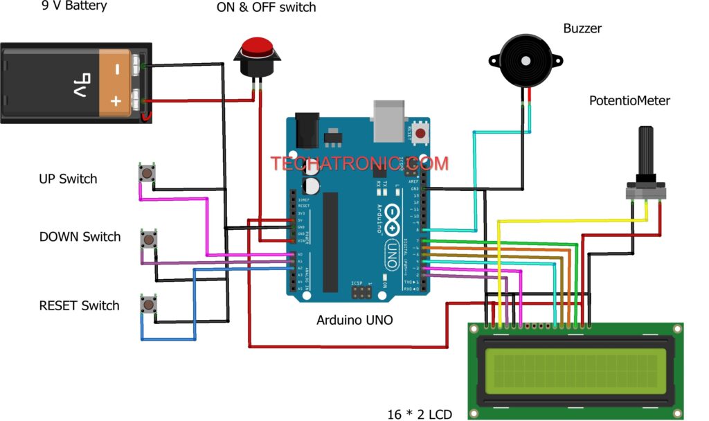
Circuit Diagram for Digital Counter
| Arduino UNO | Buzzer | ||
| D8 Pin | Positive | ||
| GND | Negative | ||
| Arduino UNO | 16*2 LCD | 10K Potentiometer | |
| GND | VSS (Ground), K | Terminal 1 | |
| +5V | VDD ( +5V ), A | Terminal 3 | |
| VEE ( Contrast ) | Terminal 2 | ||
| D12 Pin | RS ( Register Select ) | ||
| GND | RW ( Read\Write ) | ||
| D11 Pin | E ( Enable ) | ||
| D10 Pin | D4 | ||
| D9 Pin | D5 | ||
| D8 Pin | D6 | ||
| D7 Pin | D7 | ||
| Arduino UNO | Switch | Battery | |
| Terminal 1 | Positive | ||
| Vin Pin | Terminal 2 | ||
| GND | Negative | ||
| Arduino UNO | Up | Down | Reset |
| A0 Pin | Terminal 1 | ||
| A1 Pin | Terminal 1 | ||
| A2 Pin | Terminal 1 | ||
| GND | Terminal 2 | Terminal 2 | Terminal 2 |
Code for Digital CounterConnect the GND of Arduino with the pin of all the push buttons by using a breadboard such that each push button completes the circuit when you press it. Now attach the other pin of the UP push button with the analog-0 pin of the Arduino. Join the other pin of the DOWN push button with the analog-1 pin of the Arduino. Connect the other pin of the RESET push button with the analog-2 pin of the Arduino. Join a 9-volts battery with its positive wire to VIN of Arduin through a switch and negative wire to the GND of Arduino. Attach the positive wire of the buzzer with the digital-8 pin of the Arduino and the negative wire with the GND of Arduino. Now make the connections of the 16×2 LCD with the digital pins of the Arduino as shown in the diagram. Connect a 10K-ohm potentiometer with the LCD. You can check the interfacing of a 16×2 LCD with Arduino and make the connection according to it.
NOTE: Please upload the code given below to the Arduino. You have to install <EEPROM.h> and <LiquidCrystal.h> to your IDE first. Check here how to install a zip library to the Arduino IDE.
 // TECHATRONIC.COM
 // EEPROM Library LINK
 // https://github.com/PaulStoffregen/EEPROM
 #include <LiquidCrystal.h> //Libraries
 #include <EEPROM.h>
 LiquidCrystal lcd(2, 3, 4, 5, 6, 7); //Arduino pins to lcd
 #define bt_up   A0
 #define bt_down  A1
 #define bt_reset A2
 #define buzzer 8
 long d1=8, d2=7, d3=6, d4=5, d5=4, d6=3, d7=2, d8=1;
 int flag1=0, flag2=0, timer=0;
 void setup(){ // put your setup code here, to run once
  pinMode(bt_up,  INPUT_PULLUP);
  pinMode(bt_down, INPUT_PULLUP);
  pinMode(bt_reset, INPUT_PULLUP);
  pinMode(buzzer, OUTPUT);
  lcd.begin(16, 2); // Configura lcd numero columnas y filas
  lcd.clear();
  lcd.setCursor (0,0);
  lcd.print("  Welcome To  ");
  lcd.setCursor (0,1);
  lcd.print("Digital Counter");
  delay(2000);
  lcd.clear();
 if(EEPROM.read(50)==0){
 }else{WriteEeprom();}
 EEPROM.write(50,0);
 ReadEeprom();
 }
 void loop(){
 if(digitalRead (bt_up) == 0){
 if(flag1==0){ flag1=1;
 d1=d1+1;
 if(d1>9){d1=0; d2=d2+1;}
 if(d2>9){d2=0; d3=d3+1;}
 if(d3>9){d3=0; d4=d4+1;}
 if(d4>9){d4=0; d5=d5+1;}
 if(d5>9){d5=0; d6=d6+1;}
 if(d6>9){d6=0; d7=d7+1;}
 if(d7>9){d7=0; d8=d8+1;}
 if(d8>9){d8=0;}
 WriteEeprom();
  }
 }else{flag1=0;}
 if(digitalRead (bt_down) == 0){
 if(flag2==0){ flag2=1;
 d1=d1-1;
 if(d1<0){d1=9; d2=d2-1;}
 if(d2<0){d2=9; d3=d3-1;}
 if(d3<0){d3=9; d4=d4-1;}
 if(d4<0){d4=9; d5=d5-1;}
 if(d5<0){d5=9; d6=d6-1;}
 if(d6<0){d6=9; d7=d7-1;}
 if(d7<0){d7=9; d8=d8-1;}
 if(d8<0){d8=9;}
 WriteEeprom();
  }
 }else{flag2=0;}
 if(digitalRead (bt_reset) == 0){
 digitalWrite(buzzer, HIGH);
 if(timer<200){timer=timer+1;}
 if(timer==200){
 d1=0, d2=0, d3=0, d4=0, d5=0, d6=0, d7=0, d8=0;
 WriteEeprom();
 }
 }else{digitalWrite(buzzer, LOW); timer=0;}
 lcd.setCursor (0,0);
 lcd.print("Digital Counter");
 lcd.setCursor(4,1);
 lcd.print(d8);
 lcd.print(d7);
 lcd.print(d6);
 lcd.print(d5);
 lcd.print(d4);
 lcd.print(d3);
 lcd.print(d2);
 lcd.print(d1);
 delay(10);
 }
 void ReadEeprom() {
 d1=EEPROM.read(1);
 d2=EEPROM.read(2);
 d3=EEPROM.read(3);
 d4=EEPROM.read(4);
 d5=EEPROM.read(5);
 d6=EEPROM.read(6);
 d7=EEPROM.read(7);
 d8=EEPROM.read(8);
 }
 void WriteEeprom() {
 EEPROM.write(1, d1);
 EEPROM.write(2, d2);
 EEPROM.write(3, d3);
 EEPROM.write(4, d4);
 EEPROM.write(5, d5);
 EEPROM.write(6, d6);
 EEPROM.write(7, d7);
 EEPROM.write(8, d8);
 }
We hope that you understand the project completely and now try to make it on your own. While making this project if you are facing any errors feel free to discuss with us in the comments section below. Also, check out more tutorials on Arduino and Raspberry Pi.
HAPPY LEARNING!