
Hey guys, welcome back to Techatronic. You have seen the lights on the street which help in improving the clarity on roads at night. Also nowadays we can see many fancy or decorative lights on streets, highways or on bridges too that gives a perfect view of modern cities. In this article, we are going to make an automatic street light control system by using an LDR and Arduino UNO development board. There is a problem associated with the street lights that they keep on during the daytime or early in the morning when there is no need for artificial light. Sometimes the light from the sun is too bright especially in summers when the days are longer than night. Check more similar projects on Arduino. You can also check out our project on automatic street lights with IR sensors.
How Does automatic street light Work?
Do you know how an LDR sensor works with Arduino? If no then go through it once. LDR stands for the light-dependent resistor. LDR module generates its output depending upon the light which falls on its surface. During the daytime, the sunlight falls on LDR so the AC bulbs are off, and after sunset, there is no source of bright light so the AC bulbs are turned on. With this practice, a lot of electricity can be saved. We use a relay module in our project. Be careful while working with the AC load. Check here the interfacing of a relay module with Arduino. Open the Serial monitor to view the output.
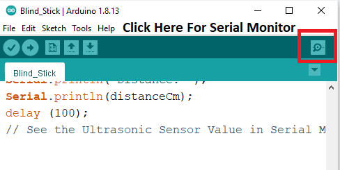

Output on Serial Monitor
- Analog connection
- Digital connection
Components Required
- Arduino UNO
- LDR sensor module
- Breadboard
- Jumper wires
- USB cable for uploading the code
- AC bulb
- Single-channel relay module
- 16×2 LCD
- 10K-ohm potentiometer
- Power supply
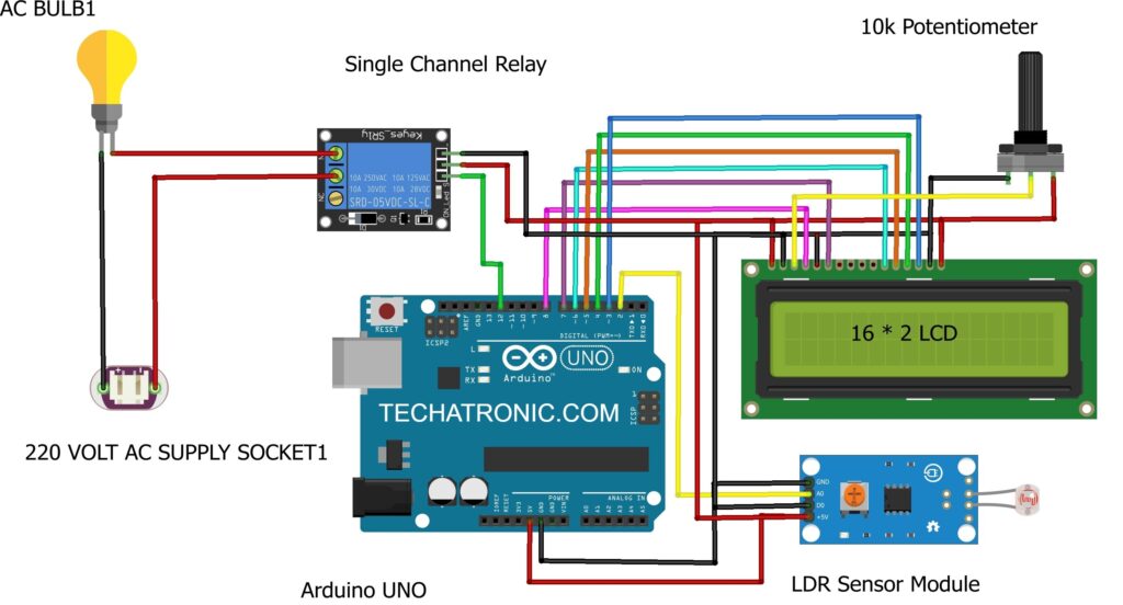
Circuit Diagram for automatic street light
- Analog connection

|
Arduino UNO |
LDR Sensor | |
|
A0 Pin |
OUT Pin | |
|
( +5V ) |
VCC | |
|
GND |
GND | |
|
Arduino UNO |
Relay Module | |
|
D12 Pin |
IN1 OUT Pin | |
|
( +5V ) |
VCC | |
|
GND |
GND | |
|
Arduino UNO |
16*2 LCD |
10K Potentiometer |
|
GND |
VSS (Ground), K |
Terminal 1 |
|
+5V |
VDD ( +5V ), A |
Terminal 3 |
|
|
VEE ( Contrast ) |
Terminal 2 |
|
D8 Pin |
RS ( Register Select ) |
|
|
GND |
RW ( Read\Write ) |
|
|
D7 Pin |
E ( Enable ) |
|
|
D6 Pin |
D4 |
|
|
D5 Pin |
D5 |
|
|
D4 Pin |
D6 |
|
|
D3 Pin |
D7 |
|
|
AC Bulb |
220 V AC Supply |
Relay Module |
|
|
|
Normally Open |
|
|
Phase |
Common |
|
Terminal 1 |
|
Normally Closed |
|
Terminal 2 |
Neutral |
|
- Digital connection
|
Arduino UNO |
LDR Sensor | |
|
D2 Pin |
OUT Pin | |
|
( +5V ) |
VCC | |
|
GND |
GND | |
|
Arduino UNO |
Relay Module | |
|
D12 Pin |
IN1 OUT Pin | |
|
( +5V ) |
VCC | |
|
GND |
GND | |
|
Arduino UNO |
16*2 LCD |
10K Potentiometer |
|
GND |
VSS (Ground), K |
Terminal 1 |
|
+5V |
VDD ( +5V ), A |
Terminal 3 |
|
|
VEE ( Contrast ) |
Terminal 2 |
|
D8 Pin |
RS ( Register Select ) |
|
|
GND |
RW ( Read\Write ) |
|
|
D7 Pin |
E ( Enable ) |
|
|
D6 Pin |
D4 |
|
|
D5 Pin |
D5 |
|
|
D4 Pin |
D6 |
|
|
D3 Pin |
D7 |
|
|
AC Bulb |
220 V AC Supply |
Relay Module |
|
|
|
Normally Open |
|
|
Phase |
Common |
|
Terminal 1 |
|
Normally Closed |
|
Terminal 2 |
Neutral |
|
Connect the 5-volts pin of the Arduino with the VCC of the relay module and 16×2 LCD. Attach the GND pin of Arduino to the GND of the relay module and 16×2 LCD. Join the data pin of the relay module with the digital-12 pin of the Arduino. Connect the pins of the LCD module with the digital GPIO pins of the Arduino as shown above. Connect the 10k-ohm potentiometer to the LCD. On the other side of the relay module connect a 220-volts AC supply and an Ac bulb. You can check how an LCD module works with Arduino and take help for connecting the pins. Attach the VCC and GND pins of the LDR module with the 5-volts and GND pin of the Arduino. Connect the D0 pin of the LDR module with the GND of Arduino. For analog connection connect the A0 pin of the LDR module with the analog-0 pin of the Arduino. If you are making a digital connection attach the A0 pin of the LDR module with the digital-2 pin of the Arduino.
Code for automatic street light
NOTE: Please upload the code given below to the Arduino. You have to install <LiquidCryatal.h> library before compiling the code. Check here how to add zip libraries to the Arduino IDE application.
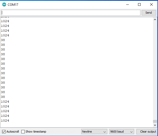
- Analog connection
 // TECHATRONIC.COM
 #include "LiquidCrystal.h"
 LiquidCrystal lcd(8,7,6,5,4,3);
 void setup()
 {
   Serial.begin(9600);
   lcd.begin(16,2);
   pinMode(12,OUTPUT);  // Relay Module Pin connected to D12
   digitalWrite(12,HIGH); // Relay Module Normaly High
 }
 void loop()
 {
  int val = digitalRead(A0); // LDR sensor output pin connected to A0
  Serial.println(val);  // see the value in serial mpnitor in Arduino IDE
  delay(100);
  if(val > 300 )
   {
    digitalWrite(12,LOW);   // Relay ON
    lcd.setCursor(0,0);
    lcd.print(" Evening Time    ");
    lcd.setCursor(0,1);
    lcd.print("  Bulb ON      ");
   }
  else
   {
    digitalWrite(12,HIGH);  // Relay OFF
    lcd.setCursor(0,0);
    lcd.print(" Morning Time    ");
    lcd.setCursor(0,1);
    lcd.print("  Bulb OFF      ");
   }
  }
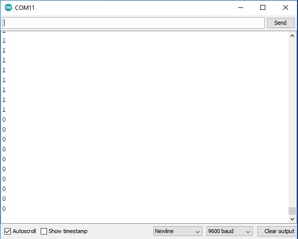
- Digital connection
 // TECHATRONIC.COM
 #include "LiquidCrystal.h"
 LiquidCrystal lcd(8,7,6,5,4,3);
 int val = 0 ;
 void setup()
 {
   Serial.begin(9600);
   lcd.init();
   lcd.backlight();
   s1.attach(9);
   pinMode(2,INPUT);   // LDR sensor output pin connected to D2
   pinMode(12,OUTPUT);  // Relay Module Pin connected to D12
   digitalWrite(12,HIGH); // Relay Module Normaly High
 }
 void loop()
 {
  val = digitalRead(2); // LDR sensor output pin connected
  Serial.println(val);  // see the value in serial mpnitor in Arduino IDE
  delay(100);
  if(val == 0 )
   {
    digitalWrite(12,LOW);   // Relay ON
    lcd.setCursor(0,0);
    lcd.print(" Evening Time    ");
    lcd.setCursor(0,1);
    lcd.print("  Bulb ON      ");
   }
  else
   {
    digitalWrite(12,HIGH);  // Relay OFF
    lcd.setCursor(0,0);
    lcd.print(" Morning Time    ");
    lcd.setCursor(0,1);
    lcd.print("  Bulb OFF      ");
   }
  }
We hope you like this project and if so, please try to make it on your own. If you are facing any errors while making this feel free to ask them in the comments section below. You can check more tutorials on Arduino and Raspberry Pi written by us.
HAPPY LEARNING!