
Table of Contents
Introduction
Hey geeks, hope you are doing fine. Do you want to make an automatic door opening and closing circuit using Arduino? Well if so then you are at the right place.
In this article, we are going to teach you how to make an automatic door using Arduino UNO and RF modules.
Before starting go through the working of an RF module with Arduino. Also, do check out more such interesting projects on Arduino and Raspberry Pi.
How Does it Work? Working
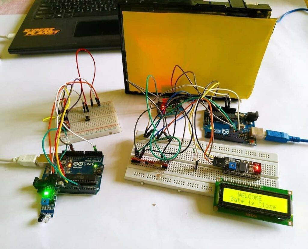
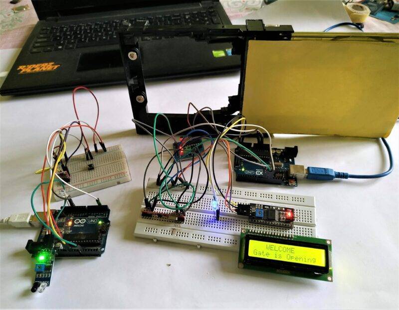
- The door will open and close automatically with the help of a DC motor which is controlled by the L298N motor driver module.
- When the IR sensor detects someone in its range, the transmitter module will send a signal to open the gate.
- If the signal is sent successfully by the module the LED will goes on. The LED keeps off in normal conditions when the IR sensor doesn’t detect someone.
- The receiver module decodes the signals and opens the gate. You have to make two separate circuits for this project.

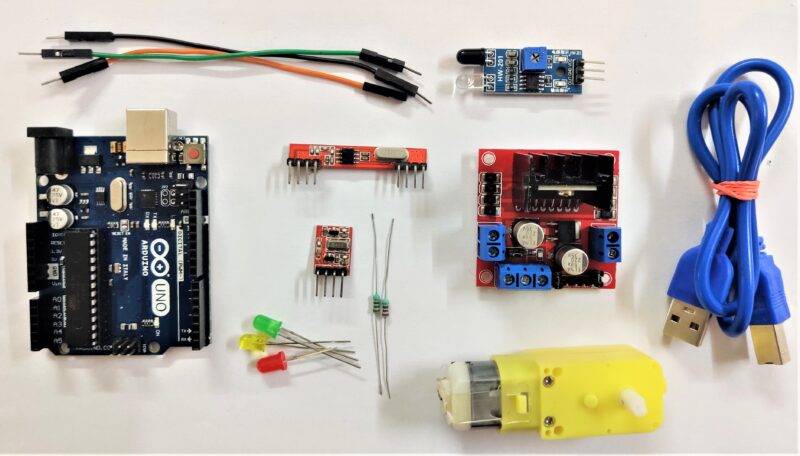
Components Required
| 2. Arduino UNO boards | BUY LINK |
| Jumper wires | BUY LINK |
| RF Transmitter Receiver module | BUY LINK |
| L298N motor driver | BUY LINK |
| LEDs | BUY LINK |
| DC motor | BUY LINK |
| IR sensor | BUY LINK |
| USB cable for uploading the code | BUY LINK |
| 9 Volt battery | BUY LINK |
| Jumper wire | BUY LINK |
| 220 Ohm resistor | BUY LINK |
Arduino RF Circuit Diagram

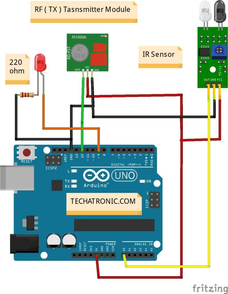
Transmitter circuit
Transmitter Connection Table
| Arduino UNO | IR Sensor | |
| ( +5V ) | VCC | |
| GND | GND | |
| A0 Pin | OUT Pin | |
| Arduino UNO | RF – Receiver Module | |
| ( +5V ) | VCC | |
| GND | GND | |
| 12 Pin | DATA Pin | |
| Arduino UNO | LED | 220 Ohm Resistor |
| 9 Pin | Anode Pin | |
| Cathode Pin | Terminal 1 | |
| GND | Terminal 2 |
- Connect the VCC pin of the RF transmitter module and the VCC pin of the IR sensor with the 5 volts pin of the Arduino.
- Join the GND pin of the RF transmitter module and the GND pin of the IR sensor with the GND pin of the Arduino.
- Connect the data pin of the transmitter module with the digital-12 pin of the Arduino.
- Take an LED and connect its positive leg with the digital-9 pin of the Arduino and the negative leg with the GND pin of the Arduino via a 220-ohm resistor.
- At last, connect the OUT pin of the IR sensor with the analog-0 pin of the Arduino. Now make the circuit for the receiver.
Receiver circuit

Receiver Connection Table
| Arduino UNO | L298N Motor Driver | |
| 7 Pin | IN 1 | |
| 6 Pin | IN 2 | |
| Arduino UNO | RF – Transmitter Module | |
| ( +5V ) | VCC | |
| GND | GND | |
| 12 Pin | DATA Pin | |
| Motor | L298N Motor Driver | |
| Terminal 1 | Terminal 1 Output | |
| Terminal 2 | Terminal 2 Output | |
| Arduino UNO | LED | 220 Ohm Resistor |
| 2 Pin | Anode Pin | |
| Cathode Pin | Terminal 1 | |
| GND | Terminal 2 | |
| Arduino UNO | 9 V Battery | L298N Motor Driver |
| ( +5V ) | +5 Volt | |
| 9 Volt | +12 Volt | |
| GND | GND | GND |
- Connect the VCC pin of the RF receiver and VCC(5 volts) pin of the motor driver with the 5 volts pin of the Arduino.
- Join the GND pin of the receiver and the GND pin of the motor driver with the GND pin of the Arduino.
- Connect a DC motor at the output pins of the motor driver. Take an LED and
- connect its positive leg with the digital-2 pin of the Arduino and the negative leg with the GND pin via a 220-ohm resistor.
- Take a 9 volts battery and connect its positive wire with the 12 volts pin of the motor driver and the negative wire with the GND pin of the Arduino.
- At last, connect the IN1 and IN2 pins of the L298N motor driver with the digital-7 and digital-6 pins of the Arduino.


Code for the Project
NOTE: Please upload the following codes according to the circuits. Install <VirtualWire.h> library to the IDE software first. Check here how to add a zip library to your Arduino IDE.
Code for the Transmitter circuit
 // Techatronic.com
 // VirtualWire Library Link
 // https://github.com/m0/Updated-Arduino-VirtualWire-Library
 #include <VirtualWire.h>
 char *controller;
 int IR_sensor;
 void setup()
 {
  // put your setup code here, to run once:
  Serial.begin(9600);
  pinMode(9,OUTPUT); // LED Pin
  vw_set_ptt_inverted(true);
  vw_set_tx_pin(12);     // DATA PIN
  vw_setup(4000);// speed of data transfer Kbps
  delay(1000);}
 void loop()
 {
 IR_sensor = analogRead(A0); // IR SENSOR PIN( A0 )
 Serial.println(IR_sensor);
 if(IR_sensor >100)
 {
   controller="1" ;
   vw_send((uint8_t *)controller, strlen(controller));
   vw_wait_tx();   // Wait until the whole message is gone
   digitalWrite(9,1); // LED ON
   delay(1000);
 }
  else
  {
   controller="0" ;
   vw_send((uint8_t *)controller, strlen(controller));
   vw_wait_tx();   // Wait until the whole message is gone
   digitalWrite(9,0); // LED OFF
  }
 }
Code for the Reciever circuit
 // Techatronic.com
 // VirtualWire Library Link
 // https://github.com/m0/Updated-Arduino-VirtualWire-Library
 #include <VirtualWire.h>
 void setup()
 {
 vw_set_ptt_inverted(true); // Required for DR3100
 vw_set_rx_pin(12); // DATA PIN
 vw_setup(4000);   // Bits per sec
 pinMode(2, OUTPUT); // LED PIN
 pinMode(6, OUTPUT); // MOTOR PIN
 pinMode(7, OUTPUT); // MOTOR PIN
 vw_rx_start(); // Start the receiver PLL running
 Serial.begin(9600);}
 void loop()
 {
 uint8_t buf[VW_MAX_MESSAGE_LEN];
 uint8_t buflen = VW_MAX_MESSAGE_LEN;
 Serial.println("starting");
 if(vw_get_message(buf, &buflen)) // Non-blocking
 {
  if(buf[0]=='1')
 {
   Serial.println("1");
   digitalWrite(2,1);  // LED ON
   digitalWrite(6,1);  // MOTOR
   digitalWrite(7,0);  // MOTOR
   delay(1000);
 }
 if(buf[0]=='0')
 {
   Serial.println("0");
   digitalWrite(2,0);  // LED ON
   digitalWrite(6,0);  // MOTOR
   digitalWrite(7,1);  // MOTOR
   delay(1000);
  }
  }
 }


We hope that you understand this project completely. If you have any doubts regarding the project then tell us in the comments section below.
Video Sample
HAPPY LEARNING!