
Table of Contents
Introduction
Hey guys, hope you are doing fine. Hall effect is a very popular principle given by the physicist Edwin hall which states that when a current-carrying conductor is introduced to a perpendicular magnetic field,
a voltage can be measured at the right angle to the current path. In this article, we are going to see the working of a Hall effect sensor with Arduino UNO board.
By using this setup we can find the magnetic field near the sensor. You can check more amazing projects on Arduino and IoT. All the necessary details regarding the project are given below in this Arduino tutorial.
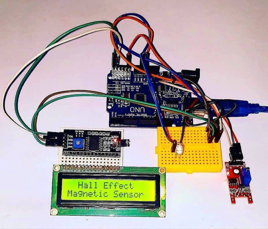
We are using a 16×2 LCD module for displaying the content. You can also check the magnet detector using Arduino, made by us.
Hall Effect Sensor Working?
- This project is helpful in detecting the magnets if present near us. It is done by the Hall effect sensor which can detect the magnetic fields emitted by strong or weak magnets.
- If the sensor detects any magnetic field the LED goes on and the buzzer starts beeping.
- The message “Magnet is Detected” can be seen on the 16×2 LCD display as well as on the serial monitor screen also.
- You can open the serial monitor from the top right corner in your Arduino IDE as shown in the image.

Simulation

Components Required
| Arduino UNO | BUY LINK |
| 16×2 LCD | BUY LINK |
| Hall effect sensor | BUY LINK |
| Buzzer | BUY LINK |
| LED | BUY LINK |
| I2C module | BUY LINK |
| Jumper wires | BUY LINK |
| breadboard | BUY LINK |
| 10K potentiometer | BUY LINK |
Components table/buy link
You can buy the whole components from the given link we have to share the amazon link. from where you can get a good discount on the components.
Hall Effect Sensor With Arduino Circuit Diagram

Connection Table
| Arduino UNO | Hall Effect Sensor | |
| ( +5V ) | ( + ) Positive | |
| GND | ( – ) Positive | |
| D5 Pin | ( S ) Signal | |
| Arduino UNO | Buzzer | |
| GND | Negative | |
| D10 Pin | Positive | |
| Arduino UNO | 16*2 LCD | 10K Potentiometer |
| GND | VSS (Ground) | Terminal 1 |
| +5 Volt | VDD ( +5V ) | Terminal 3 |
| VEE ( Contrast ) | Terminal 2 | |
| A0 Pin | RS ( Register Select ) | |
| GND | RW ( Read\Write ) | |
| A1 Pin | E ( Enable ) | |
| A2 Pin | D4 | |
| A3 Pin | D5 | |
| A3 Pin | D6 | |
| A4 Pin | D7 | |
| Arduino UNO | LED | 220-ohm Resistor |
| D9 Pin | Anode Terminal | |
| GND | Terminal 1 | |
| Cathode Terminal | Terminal 2 |
- Connect the 5 volts pin of the Arduino with the VCC of the Hall sensor and the GND pin of the Arduino with the GND pin of the Hall sensor.
- Join the data pin of the Hall sensor with the digital-5 pin of the Arduino.
- Take a 10K ohm preset and connect its pins with the 16×2 LCD module.
- Join the negative wires of the buzzer and LED with the GND pin of the Arduino via a 220-ohm resistor.
- Connect the positive leg of the LED with the digital-9 pin of the Arduino and the positive wire of the buzzer with the digital-10 pin of the Arduino.
- Attach the pins of the 16×2 LCD with the analog pins of the Arduino as shown in the diagram.
You can also take help from one of our articles on the working of 16×2 LCD. If you want to use an I2C module for interfacing with the LCD then Connect its VCC and GND pins with the 5 volts pin and the GND pin of the Arduino.
View the connections of the I2C module with LCD here. Also, check the address of the I2C module that you are using.
Arduino Hall Effect Sensor Code for the Project
NOTE: Please upload the code which is given below to the Arduino.
Try to make this project by yourself for better understanding. If you have any doubts regarding the project then tell us in the comments section below. You can read the latest tutorials on Arduino and Raspberry Pi written by us.
HAPPY LEARNING!