

Table of Contents
Introduction
Welcome to Techatronic. In this article, we will learn how to make RF Module Control Push Button Using Arduino.
Arduino is a microcontroller that uses ATmega328p IC for its functioning.
There are many types of Arduino boards available but in this project, we use Arduino UNO. This project uses Arduino UNO and RF Transmitter and a Reciever to send the signals by tapping the push button so the LED turns on and off.
If you have an interest in Arduino and related projects do check out here for more. The Transmitter Module is connected to one of the Arduino and the Reciever module is connected with the other one.
Follow the easy steps given below to complete the circuit diagram and then upload the Arduino code in this Arduino Tutorial. You can also check out Interfacing GSM Module with Arduino.
How Does It Work?
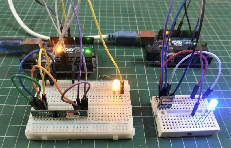
In this project, we use two Arduino UNO with the RF Transmitter and Reciever Module.
- The Transmitter is used to send the signal to the desired destination and the Receiver is used to receive the transmitted signal.
- A push-button is connected to the Transmitter circuit to send the signals. Want to know how push-button works with Arduino click here. When we press the push-button the LED connected with the Reciever circuit will glow.
- Arduino Tutorial for rf receiver is given here. This indicates that we successfully send the signal and receive it at the other end. Read the instructions given below carefully to make your own project.
Components Required
- RF Transmitter and Reciever Module
- Two Arduino UNO
- Breadboard
- Two LED and Towel Switch
- 220-ohm Resistors and a 10K ohm resistor
- Jumper Wires
- USB cable to Upload the Code
Components Table/ buy link
You can buy the whole components from the given link we have to share the amazon link. from where you can get a good discount on the components.
Circuit Diagram of the Project
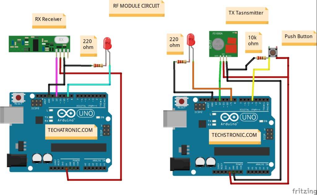
Make the connections according to the given circuit diagram.
- Connect the 5 Volt pin of one of the Arduino with the VCC of the Transmitter module and a side of the Push-button. Join the GND pin of the Arduino to the GND of the Transmitter module and
- another side of the Pushbutton through a resistor as shown and then
- connect it with the digital 4 pin of the Arduino.
- Connect the data pin of the Transmitter module to the digital 12 pin of the Arduino.
- Join the positive leg of LED with the digital 9 pin of Arduino and the negative leg to the ground through a resistor.
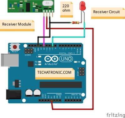
Receiver Circuit
Receiver Circuit Table
| Arduino UNO | RF – Receiver Module | |
| ( +5V ) | VCC | |
| GND | GND | |
| 12 Pin | DATA Pin | |
| Arduino UNO | LED | 220 Ohm Resistor |
| 9 Pin | Anode Pin | |
| Cathode Pin | Terminal 1 | |
| GND | Terminal 2 |
- Connect the 5 Volt pin of the Arduino to the VCC of the Reciever Module GND to the Ground of Arduino.
- Join the positive leg of the LED to the digital 9 pin of Arduino and negative to the GND through a resistor.
- Attach the data pin of the Reciever Module to the digital 12 pin Arduino.
- After making the connections upload the code given below for both of the Arduino.
Transmitter Circuit

| Arduino UNO | RF – Transmitter Module | |
| ( +5V ) | VCC | |
| GND | GND | |
| 12 Pin | DATA Pin | |
| Arduino UNO | LED | 220 Ohm Resistor |
| 9 Pin | Anode Pin | |
| Cathode Pin | Terminal 1 | |
| GND | Terminal 2 | |
| Arduino UNO | Push Button | 10K ohm Resistance |
| 4 Pin | Terminal 1 | Terminal 1 |
| + 5 VCC | Terminal 2 | |
| GND | Terminal 2 |
Code of the Project
Note: Upload the code given below to both of the Arduino. You need to install the library <VirtualWire.h>.
Code for the Reciever Circuit
 #include <VirtualWire.h>
 void setup()
 {
 vw_set_ptt_inverted(true); // Required for DR3100
 vw_set_rx_pin(12);
 vw_setup(4000); // Bits per sec
 Serial.begin(9600);
 pinMode(9, OUTPUT);
 vw_rx_start(); // Start the receiver PLL running
 }
 void loop()
 {
 uint8_t buf[VW_MAX_MESSAGE_LEN];
 uint8_t buflen = VW_MAX_MESSAGE_LEN;
   Serial.println();
 if (vw_get_message(buf, &buflen)) // Non-blocking
 {
 if(buf[0]=='0')
 {
 digitalWrite(9,HIGH);
 }
 else
 {
 digitalWrite(9,LOW);
 }
 }
 }
Code for the Transmitted Circuit
 #include <VirtualWire.h>
 char *controller;
 const int buttonPin1 = 2;
 int buttonState1 = 0;
 void setup()
 {
  // put your setup code here, to run once:
 Serial.begin(9600);
 pinMode(buttonPin1, INPUT);
 pinMode(9,OUTPUT);
 vw_set_ptt_inverted(true); //
 vw_set_tx_pin(12);
 vw_setup(4000);// speed of data transfer Kbps
 delay(100);}
 void loop()
 {
   buttonState1 = digitalRead(buttonPin1);
   Serial.println(controller);
  if (buttonState1 == HIGH)
 {
 controller="1" ;
 vw_send((uint8_t *)controller, strlen(controller));
 vw_wait_tx(); // Wait until the whole message is gone
 digitalWrite(9,LOW);
 }
  else
  {
  controller="0" ;
 vw_send((uint8_t *)controller, strlen(controller));
 vw_wait_tx(); // Wait until the whole message is gone
 digitalWrite(9, HIGH);
  }
 }
Hope you understand the project well. If you are facing any errors do inform us in the comment section below.
HAPPY LEARNING!
Sponsor:

Make a wireless remote Custom PCB by just ordering your PCB at NextPCB. Upload your Gerber files to get high quality, professional-looking 1,2,4, etc. layers looking PCB at a reasonable price. They provide PCB manufacturing service also PCB Assembly service for SMD components with multiple testing, AOI, X-Ray testing for your order before it departs their pass check. So why just wait and order one for you at NextPCB and make your DIY project into a professional one.