
Table of Contents
Introduction
Hello There. Welcome to Techatronic. In this article, We will see the interfacing of the SIM 900 GSM Module with Arduino.
I hope you will find this article helpful. If you Are building a project using this module or need something to control your project from a faraway place without internet.
you will find this helpful. We will also look into the working of the module to know more about it. On our website,
we have already uploaded a lot many Arduino tutorials and Arduino projects. You may check them if you are a beginner in electronics and learn more. You may also find some cool DIY projects using Arduino.
What is GSM SIM 900 Module?
- The GSM SIM 900 Module is a type of Arduino Shield, which means it can also be mounted on top of Arduino UNO.
- This is a type of modem, used for long-distance data transmission with the use of GSM technology where there is no internet connectivity.
- this makes it useful in projects which require remote data transmission. Many projects can be made using this module such as call or text message-based triggers which can be used in our day-to-day life.
- To make electronics projects on the gsm module you must read this gsm tutorial.
- Farmers can extensively use this technology in their day-to-day life, such as controlling water pumps with a simple silent call or a text message sitting at their home.
- for example gsm based agriculture project. This can also be used to send the data from the module to our mobile phones without the use of the internet.
Other project ideas include intruder alert notification, Receive timely updates from the sensor to your mobile, etc.
How Does the SIM 900 Module work?
The GSM module uses GSM and GPRS technology to communicate with another device wirelessly. It uses 2G network to connect with the internet and supports Quad-band(EGSM 900, GSM 850, DCS 1800, PCS1900).
Because of this, one can send or receive messages from this or make or receive voice calls using the module by connecting the microphone and speakers to the respective ports given on it.
this module can be used for security purposes like gsm-based forest fire alerts and control system.
This Module also houses an inbuilt RTC to keep track of time, which is very helpful for timer-based applications.
the versatility of this module is very high due to its ability to read and send messages without any hassle.
Because of the use of AT Commands, it is very easy to configure. because of the presence of an external antenna, the module can also be used in areas with low signal areas.
Check Our latest Arduino Projects And IOT Projects

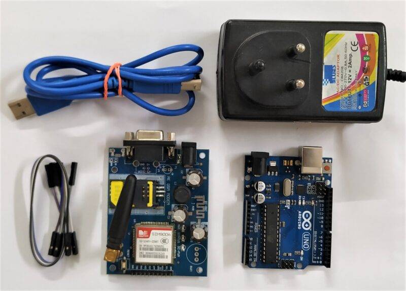
Components Required
- Arduino UNO
- SIM 900 GSM Module
- Full-Size SIM Card (Unlocked)
- 12V 2Amp Power Supply
- Connecting Wires
- Breadboard
- USB cable for uploading code into Arduino UNO
| Arduino UNO | BUY LINK |
| SIM 900 GSM Module | BUY LINK |
| Full-Size SIM Card (Unlocked) | BUY LINK |
| 12V 2Amp Power Supply | BUY LINK |
| Connecting Wires | BUY LINK |
| Breadboard | BUY LINK |
| Arduino UNO Cable | BUY LINK |
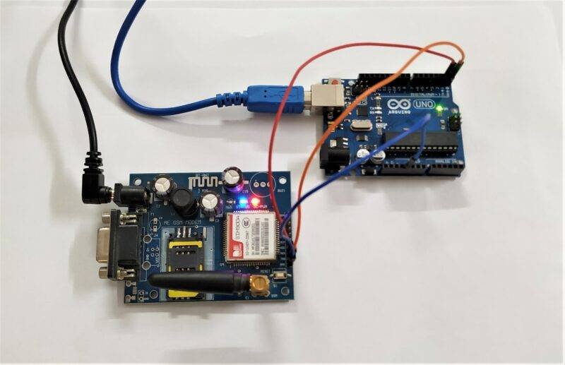
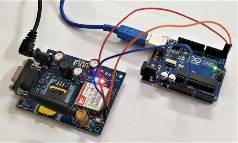
Interfacing GSM Module with Arduino Circuit Diagram
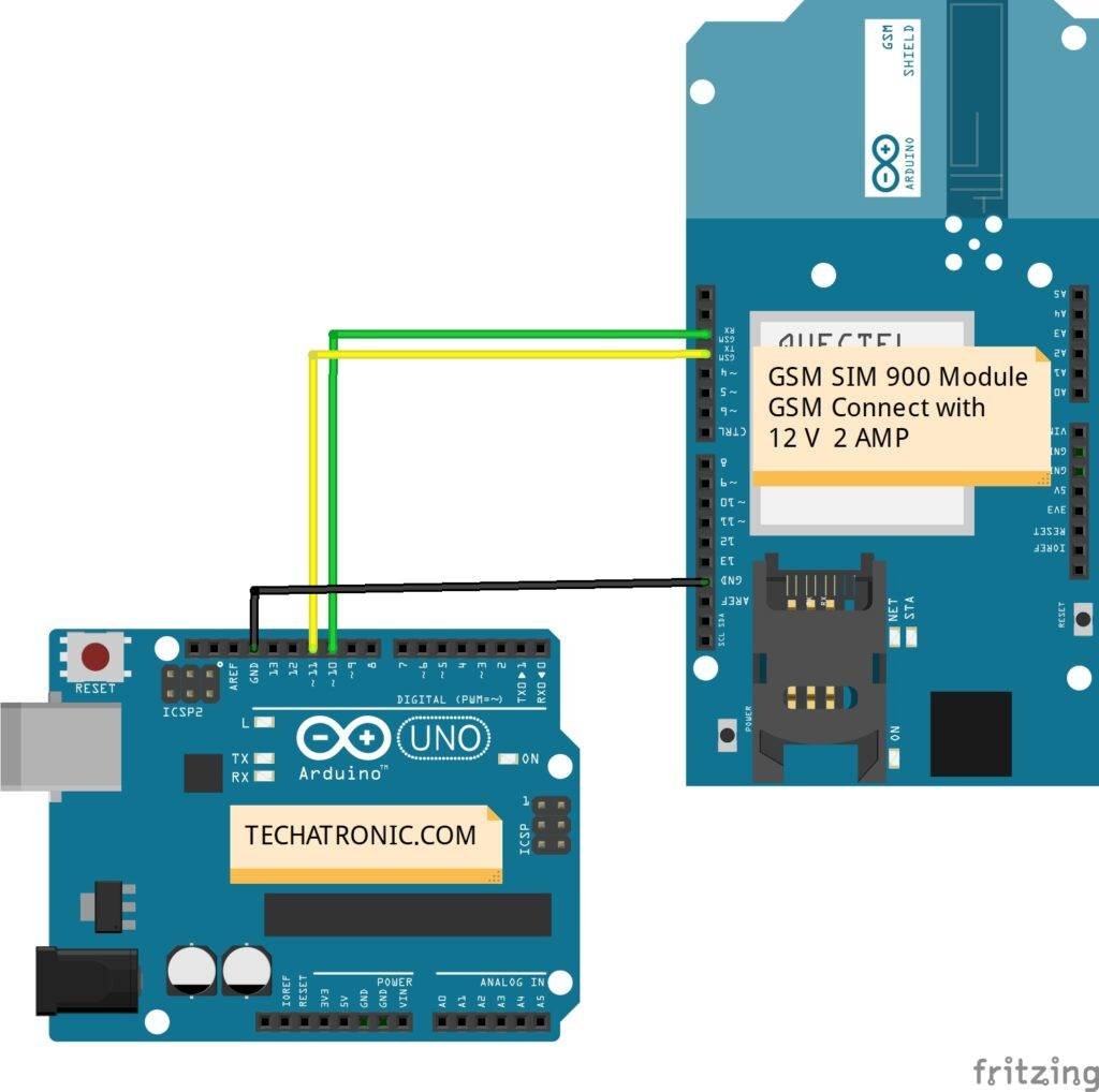
Connection Table
| Arduino UNO | GSM SIM 900 Module |
| TX | RX |
| RX | TX |
| GND | GND |
| 12 Volt 2 Amp Adaptor | GSM SIM 900 Module |
| Connect | Connect |
Commands Use for Operation
AT Commands:-
|
Command
|
Description
|
|
AT+CSMS
|
To Select message service
|
|
AT+CPMS
|
To Preferred message storage
|
|
AT+CMGF
|
select Message format
|
|
AT+CSCA
|
Service center address
|
|
AT+CSMP
|
Set text mode parameters in sim
|
|
AT+CSDH
|
To Show text mode parameters in Sim
|
|
AT+CSCB
|
Select cell broadcast message types
|
|
AT+CSAS
|
Save settings in the gsm module
|
|
AT+CRES
|
Restore all settings
|
|
AT+CNMI
|
Message indications to TE
|
|
AT+CMGL
|
To make the list of messages
|
|
AT+CMGR
|
Read new message
|
|
AT+CMGS
|
Send a new message
|
|
AT+CMSS
|
Send message from sim storage
|
|
AT+CMGW
|
Write a message to gsm memory
|
|
AT+CMGD
|
Delete message
|
Interfacing GSM Module with Arduino Code
NOTE: Before uploading the code, Download the serial software library from HERE and install it in your Arduino IDE.
 // Techatronic.com
 // Download Library of SoftwareSerial link given
 // https://github.com/PaulStoffregen/SoftwareSerial
 #include <SoftwareSerial.h>
 SoftwareSerial SIM900A(10,11); // SoftSerial( RX , TX );
 // 10 pin connect to TX of GSM SIM 900 Module
 // 11 pin connect to RX of GSM SIM 900 Module
 void setup()
 {
  SIM900A.begin(9600);  // Setting the baud rate of GSM Module
  Serial.begin(9600);  // Setting the baud rate of Serial Monitor (Arduino)
  Serial.println ("SIM900A Ready");
  delay(100);
  Serial.println ("Type s to send message or r to receive message");
 }
 void loop()
 {
  if (Serial.available()>0)
   switch(Serial.read())
  {
   case 's':
    SendMessage();
    break;
   case 'r':
    RecieveMessage();
    break;
  }
  if (SIM900A.available()>0)
   Serial.write(SIM900A.read());
 }
  void SendMessage()
 {
  Serial.println ("Sending Message");
  SIM900A.println("AT+CMGF=1");  //Sets the GSM Module in Text Mode
  delay(1000);
  Serial.println ("Set SMS Number");
  SIM900A.println("AT+CMGS=\"911234567890\"\r"); //Type Your Mobile number to send message
  delay(1000);
  Serial.println ("Set SMS Content");
  SIM900A.println("Good morning, how are you doing?");// Messsage content
  delay(100);
  Serial.println ("Finish");
  SIM900A.println((char)26);// ASCII code of CTRL+Z
  delay(1000);
  Serial.println ("Message has been sent ->SMS Selesai dikirim");
 }
  void RecieveMessage()
 {
  Serial.println ("SIM900A Membaca SMS");
  delay (1000);
  SIM900A.println("AT+CNMI=2,2,0,0,0"); // AT Command to receive a live SMS
  delay(1000);
  Serial.write ("Unread Message done");
  }
GSM Projects
Call And Message Using Arduino And Gsm Module | GSM Tutorial | Arduino GSM project
Send And Receive SMS Using SIM900 GSM Module
Digitalize GSM based Forest fire alert system | major project for ECE
GSM Based fire alarm Project | Final year project for ECE using GSM
GSM based home automation using Arduino & Sim900
Before Uploading the code put the SIM card inside the given socket. After the code is uploaded and powering the module with an external supply, you may see the serial monitor open. Hence your code is running properly. I hope you found this article helpful. If you have any queries or doubts, you can ask them in the comment section below.
