
Table of Contents
Introduction
Hey Geeks, welcome back to Techatronic. Are you looking for a GSM-based SMS and calls-making project, well if so then you are at the right destination.
In this article,
we are going to discuss how you can send and receive SMS using an Arduino with the help of a SIM900 GSM module. Also,
check out more amazing projects on Arduino and read our Arduino E-book which contains 10+ projects with complete circuits and codes.
We have to program the Arduino for making calls or sending, receiving SMS. In this project, we are going to explain how to send messages and receive messages by the AT commands.

sim900 gsm module working?
- Connect a DC 12-volts 2 Amp power supply to the DC jack of the GSM sim-900 module. I
- nsert a sim into the given slot in the GSM module.
- We are using AT commands in the code for performing various functions in which AT stands for attention.
- The AT+CMGF=1 is used to select the operating mode of the GSM module.
- The AT+CMGS is used to send the SMS message. AT+CNMI,

this AT command is used to receive a live SMS.
- we are sending and receiving SMS and make calls using a GSM module with an Arduino UNO microcontroller board.
- You can check the interfacing of a SIM900 GSM module with Arduino if you don’t know about it.
- Please complete the circuit and then upload the given code to the Arduino for performing the desired operation. .
- To make a call type “C”, to receive an SMS type “R”, to send an SMS type “S” in the serial monitor.
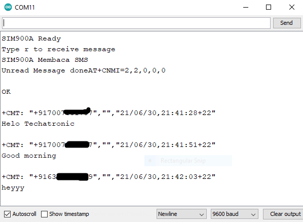
- Use the image given below to locate the serial monitor. We attach some screenshots of the output on the serial monitor.
- Please write the contact number of the sim you are using in the code so that you can operate the GSM module.
- You can also check to digitalize the GSM-based forest fire alert system made by us for performing different operations you have to specify the instruction in the serial monitor

Software Simulation

Sending Message to GSM SIM 900 Module
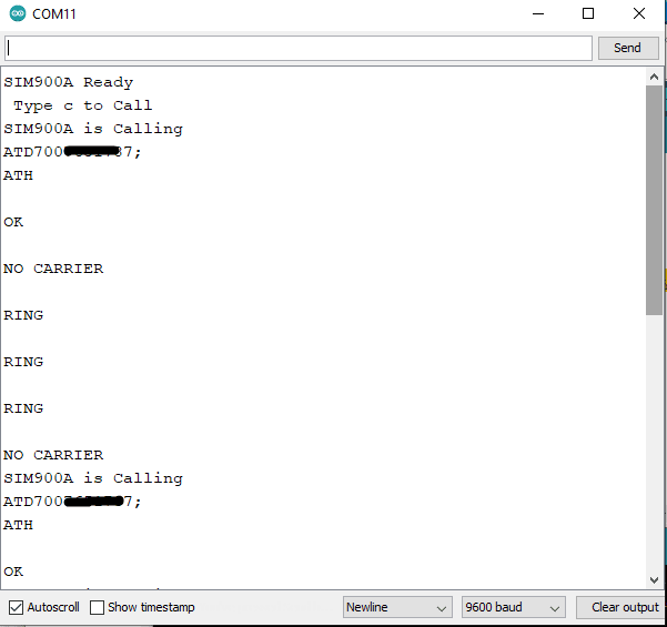
Calling GSM SIM 900 Module
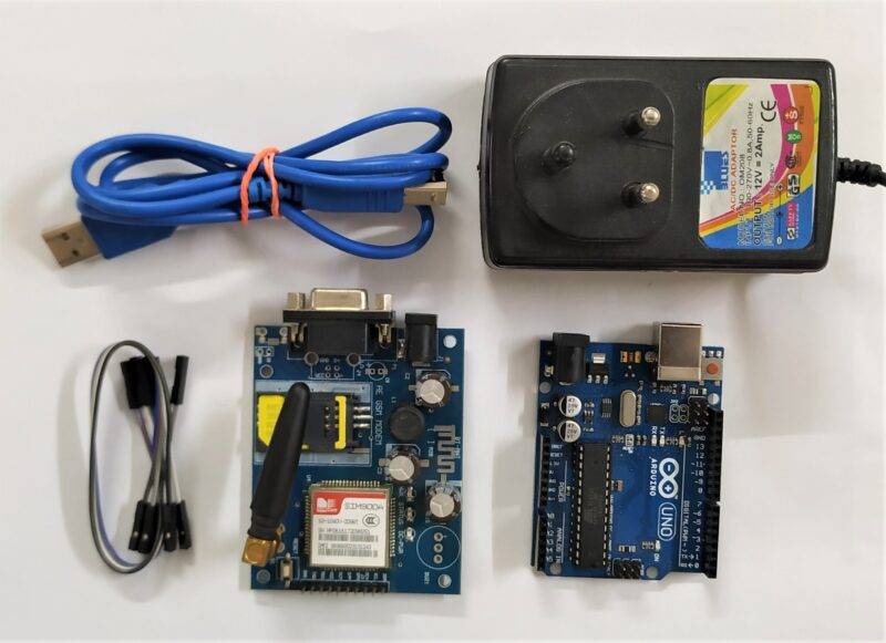
Components Required
| Arduino UNO | BUY LINK |
| GSM SIM 900 Module | BUY LINK |
| USB cable for uploading the code | BUY LINK |
| DC 12-volts 2 Amp Adapter | BUY LINK |
| Jumper wires | BUY LINK |
| Breadboard | BUY LINK |
Circuit Diagram for the Project

Connection Table
| Arduino UNO | GSM SIM 900 Module |
| D 11 Pin | RX |
| D 10 Pin | TX |
| GND | GND |
| 12 Volt 2 Amp Adaptor | GSM SIM 900 Module |
| Power Connect | Connect |
- Make the connections according to the circuit diagram given above.
- Connect the GND pin of the Arduino with the GND pin of the GSM module.
- Attach the digital-11 pin of the Arduino to the RX pin of the GSM module.
- Join the digital-10 pin of the Arduino with the TX pin of the GSM module.
AT Commands:-
|
Command
|
Description
|
|
AT+CSMS
|
To Select message service
|
|
AT+CPMS
|
To Preferred message storage
|
|
AT+CMGF
|
select Message format
|
|
AT+CSCA
|
Service center address
|
|
AT+CSMP
|
Set text mode parameters in sim
|
|
AT+CSDH
|
To Show text mode parameters in Sim
|
|
AT+CSCB
|
Select cell broadcast message types
|
|
AT+CSAS
|
Save settings in the gsm module
|
|
AT+CRES
|
Restore all settings
|
|
AT+CNMI
|
Message indications to TE
|
|
AT+CMGL
|
To make the list of messages
|
|
AT+CMGR
|
Read new message
|
|
AT+CMGS
|
Send a new message
|
|
AT+CMSS
|
Send message from sim storage
|
|
AT+CMGW
|
Write a message to gsm memory
|
|
AT+CMGD
|
Delete message
|
Code for the Project
NOTE: Please upload the codes given below one by one to the Arduino for performing different functions. You need to install <SoftwareSerial.h> library before uploading the code. Please check how to install zip libraries to the Arduino if you don’t know.
Code for sending SMS
 // Techatronic.com
  // Download Library of SoftwareSerial link given
  // https://github.com/PaulStoffregen/SoftwareSerial
  #include <SoftwareSerial.h>
  SoftwareSerial SIM900A(10,11); // SoftSerial( RX , TX );
  // 10 pin connect to TX of GSM SIM 900 Module
  // 11 pin connect to RX of GSM SIM 900 Module
  void setup()
  {
  SIM900A.begin(9600); // Setting the baud rate of GSM Module
  Serial.begin(9600); // Setting the baud rate of Serial Monitor (Arduino)
  Serial.println ("SIM900A Ready");
  delay(100);
  Serial.println ("Type s to send message ");
  }
  void loop()
  {
  if (Serial.available()>0)
   switch(Serial.read())
  {
   case 's':
   SendMessage();
   break;
  }
  if (SIM900A.available()>0)
   Serial.write(SIM900A.read());
  }
  void SendMessage()
  {
  Serial.println ("Sending Message");
  SIM900A.println("AT+CMGF=1"); //Sets the GSM Module in Text Mode
  delay(1000);
  Serial.println ("Set SMS Number");
  SIM900A.println("AT+CMGS=\"xxxxxxxxxx\"\r"); //Write Mobile number to send message
  delay(1000);
  Serial.println ("Set SMS Content");
  SIM900A.println("Helo, Techatronic.com");// Messsage content
  delay(100);
  Serial.println ("Finish");
  SIM900A.println((char)26);// ASCII code of CTRL+Z
  delay(1000);
  Serial.println ("Message has been sent ->SMS Selesai dikirim");
  }
Code for receiving SMS
 // Techatronic.com
  // Download Library of SoftwareSerial link given
  // https://github.com/PaulStoffregen/SoftwareSerial
  #include <SoftwareSerial.h>
  SoftwareSerial SIM900A(10,11); // SoftSerial( RX , TX );
  // 10 pin connect to TX of GSM SIM 900 Module
  // 11 pin connect to RX of GSM SIM 900 Module
  void setup()
  {
  SIM900A.begin(9600); // Setting the baud rate of GSM Module
  Serial.begin(9600); // Setting the baud rate of Serial Monitor (Arduino)
  Serial.println ("SIM900A Ready");
  delay(100);
  Serial.println ("Type r to receive message");
  }
  void loop()
  {
  if (Serial.available()>0)
   switch(Serial.read())
  {
   case 'r':
   RecieveMessage();
   break;
  }
  if (SIM900A.available()>0)
   Serial.write(SIM900A.read());
  }
  void RecieveMessage()
  {
  Serial.println ("SIM900A Membaca SMS");
  delay (1000);
  SIM900A.println("AT+CNMI=2,2,0,0,0"); // AT Command to receive a live SMS
  delay(1000);
  Serial.write ("Unread Message done");
  }
Code for calling and ringing
 // Techatronic.com
  // Download Library of SoftwareSerial link given
  // https://github.com/PaulStoffregen/SoftwareSerial
  #include <SoftwareSerial.h>
  SoftwareSerial SIM900A(10,11); // SoftSerial( RX , TX );
  // 10 pin connect to TX of GSM SIM 900 Module
  // 11 pin connect to RX of GSM SIM 900 Module
  void setup()
  {
  SIM900A.begin(9600); // Setting the baud rate of GSM Module
  Serial.begin(9600); // Setting the baud rate of Serial Monitor (Arduino)
  Serial.println ("SIM900A Ready");
  delay(100);
  Serial.println (" Type c to Call ");
  }
  void loop()
  {
  if (Serial.available()>0)
   switch(Serial.read())
  {
   case 'c':
   RecieveMessage();
   break;
  }
  if (SIM900A.available()>0)
   Serial.write(SIM900A.read());
  }
  void RecieveMessage()
  {
  Serial.println ("SIM900A is Calling");
  delay (1000);
   SIM900A.println("ATDxxxxxxxxxx;"); //replace x by your number
   delay(100);
   SIM900A.println("ATH");
  }
Related Projects
Interfacing GSM Module with Arduino| SIM 900 Module | GSM Tutorial
Digitalize GSM based Forest fire alert system | major project for ECE
GSM Based fire alarm Project | Final year project for ECE using GSM
GSM based home automationCall And Message Using Arduino And Gsm Module | GSM Tutorial | Arduino GSM project using Arduino & Sim900
We hope that you like this project and if so please try to make it on your own. Also, check out more tutorials on Arduino and Raspberry Pi made by us. If you are facing any problems let us know in the comments section below.
HAPPY LEARNING!
Video Sample