
Hey, guys welcome back to Techatronic. Today we are going to share a very good project with all detail like code, circuit, and making instructions the project name is Password based door lock system using Arduino with Keypad.
Table of Contents
Introduction
this is a very cool project and can be used in mini as well as a major project. or you can make one password-based door lock system for your home too.
you can use this lock at your office and in many other places. if you will buy the same lock from the market it will be costly but if you want to own that lock you can make it by this project.
what you have to do to make this project is read the full article carefully and follow all the instructions. if you have some basics of Arduino or electronics you can make this easily otherwise go to our website in the blog section go to the basic electronic and Arduino tutorial.
A preview image of Obstacle avoiding robot can be different from your own.

In this project,
you will learn how to interface the hex keypad with Arduino.
4×4 keypad also known as the hex keypad. the keypad uses the matrix principle to find out the pressed key.
there is a total of 16 keys, 4 rows, and 4 columns. and 8 connecting wires to connect with the Arduino.
there is no ground and VCC wire to connect to the power.
because there are no electronic components inside the keypad there is only the combination of circuit and wires.
the project password-based door lock system is also known as the password-based circuit breaker. circuit breaker means here when it complies with the conditions then the circuit will be break.
so as this project there is also many other security lock project like fingerprint sensor based lock system also works the same when the right fingerprint place on the fingerprint it will break the circuit. now we will talk about the working of the system.
How does the keypad Arduino lock works?/ Working
- The system contents three devices. input, process, and output device. the input device is the keypad.
- which will send all the input data to the next device which is Arduino.
- Arduino works here as a processing device.
- there is a matrix of 4×4 inside the keypad.
- and there are the 16 circuits when we press any key then anyone of the circuit will turn on. if we press the A key then the circuit below the button will activate and send this information to the Arduino.
before the keypress, all the circuit is turned off. the row and column make the circuit with the combination in a password-based door lock system using Arduino.
- when we press the key then the Arduino gets notified that which circuit is activated right now.
- and there is a character assigned with the circuit which can be shown on the serial monitor
- if you have some basic knowledge then you can easily observe the character into the serial monitor.
- and there may be errors occurred sometimes to get the right character which you can easily sort out.
this is basically a user-defined password-based circuit breaker in the Arduino project where you need to make your own password now how you can enter the password.
first, it will ask you the password to enroll then enter the 12345 into the password and now you can make your own password and the process is given here.
when we press the key Arduino gets the character now and then the character will save into the Arduino memory and then you need to enter another three characters to enroll the password into the system.
and then you can make this password the current password. this is pretty easy if you have any confusion to make the password we will give you the video in the last section of the post.
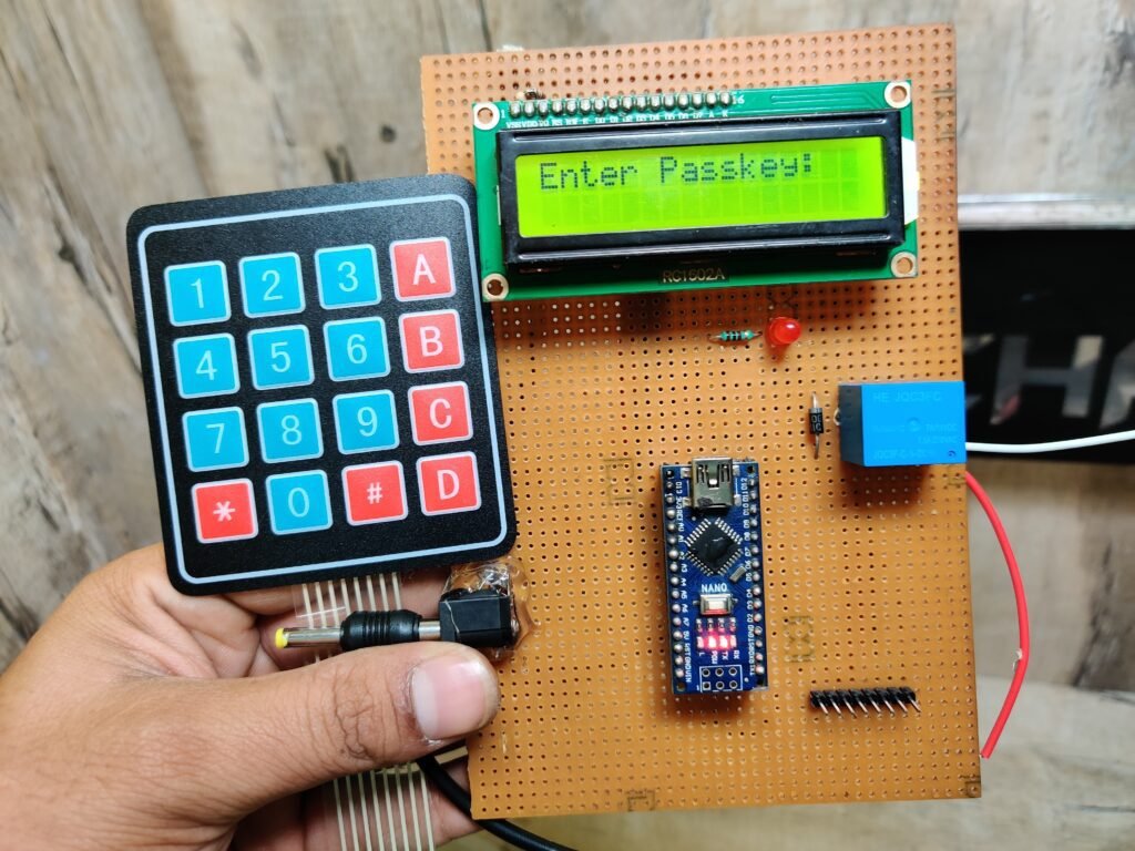
Components Required to make Password based door lock system using Arduino
- Arduino Nano
- Arduino nano cable
- LED
- 220-ohm Resistor
- 5V Relay
- Solenoid lock
- Zero PCB
- Soldering Iron
- Soldering Wire
- Hookup wire.
- 16×2 LCD
- Breadboard
- Jumper Wire
Keypad Arduino Circuit Diagram:-
we are also using a Solenoid lock which will be used after the relay. when the keypad lock system gets the right password then the Arduino sends high on the mentioned pin and the relay will be open and also the solenoid lock will be open. here we are using a 12v solenoid lock.

Connection Table
| Arduino UNO | 4*4 Keypad | |
| A0 Pin | Row 1 | |
| A1 Pin | Row 1 | |
| 8 Pin | Row 1 | |
| 9 Pin | Row 1 | |
| 10 Pin | Column 1 | |
| 11 Pin | Column 1 | |
| 12 Pin | Column 1 | |
| 13 Pin | Column 1 | |
| Arduino UNO | 5V single channel Relay | |
| +5V | VCC | |
| GND | GND | |
| 2 Pin | IN ( Input Pin ) | |
| Arduino UNO | Buzzer | |
| GND | Negative | |
| A4 Pin | Positive | |
| Arduino UNO | 16*2 LCD | 10K Potentiometer |
| GND | VSS (Ground) | Terminal 1 |
| +5V | VDD ( +5V ) | Terminal 3 |
| VEE ( Contrast ) | Terminal 2 | |
| 7 Pin | RS ( Register Select ) | |
| GND | RW ( Read\Write ) | |
| 6 Pin | E ( Enable ) | |
| 5 Pin | D4 | |
| 4 Pin | D5 | |
| 3 Pin | D6 | |
| 2 Pin | D7 | |
| 12 Volt Adaptor | 5V single channel Relay | 12 Volt Solenoid |
| Normally Open | Positive (+ ) | |
| Positive Pin (+) | Common | |
| Normally Closed | ||
| Negative Pin ( – ) | Negative( – ) | |
| Arduino UNO | LED | Resistor |
| A3 | Anode Pin | |
| Cathode Pin | Terminal 1 | |
| GND | Terminal 2 |
Keypad 4×4 Arduino CodeHere we are using a 12v power supply for the solenoid and we need to power the Arduino with the 5v power supply in this Arduino project or we can use the same supply but for the Arduino, we can use a buck converter.
and if you are using a different power supply then you need to common the ground pin of both supplies. make sure the power supply is off during the connection. if you have any problem you can ask us in the comment section.
 #include <Keypad.h>
 #include<LiquidCrystal.h>
 #include<EEPROM.h>
 #define led A3
 #define buzzer A4
 LiquidCrystal lcd(7,6,5,4,3,2);
 char password[4];
 char pass[4],pass1[4];
 int i=0;
 char customKey=0;
 const byte ROWS = 4; //four rows
 const byte COLS = 4; //four columns
 char hexaKeys[ROWS][COLS] = {
  {'1','2','3','A'},
  {'4','5','6','B'},
  {'7','8','9','C'},
  {'*','0','#','D'}
 };
 byte rowPins[ROWS] = {A0, A1, 8, 9}; //connect to the row pinouts of the keypad
 byte colPins[COLS] = {10, 11, 12, 13}; //connect to the column pinouts of the keypad
 //initialize an instance of class NewKeypad
 Keypad customKeypad = Keypad( makeKeymap(hexaKeys), rowPins, colPins, ROWS, COLS);
 void setup()
 {
  lcd.begin(16,2);
  pinMode(led, OUTPUT);
  pinMode(buzzer, OUTPUT);
  pinMode(1, OUTPUT);
  //  pinMode(m12, OUTPUT);
  lcd.print(" Electronic ");
  lcd.setCursor(0,1);
  lcd.print(" Keypad Lock ");
  delay(2000);
  lcd.clear();
  lcd.print("Enter Ur Passkey:");
  lcd.setCursor(0,1);
  for(int j=0;j<4;j++)
  EEPROM.write(j, j+49);
  for(int j=0;j<4;j++)
  pass[j]=EEPROM.read(j);
 }
 void loop()
 {
  customKey = customKeypad.getKey();
  if(customKey=='#')
  change();
  if (customKey)
  {
    password[i++]=customKey;
    lcd.print(customKey);
    beep();
  }
  if(i==4)
  {
   delay(200);
   for(int j=0;j<4;j++)
   pass[j]=EEPROM.read(j);
   if(!(strncmp(password, pass,4)))
   {
     digitalWrite(1, HIGH
     );
    digitalWrite(led, HIGH);
    beep();
    lcd.clear();
    lcd.print("Passkey Accepted");
    delay(2000);
    lcd.setCursor(0,1);
    lcd.print("#.Change Passkey");
    delay(2000);
    lcd.clear();
    lcd.print("Enter Passkey:");
    lcd.setCursor(0,1);
    i=0;
    digitalWrite(led, LOW);
     digitalWrite(1, LOW);
   }
   else
   {
    digitalWrite(buzzer, HIGH);
    lcd.clear();
    lcd.print("Access Denied...");
    lcd.setCursor(0,1);
    lcd.print("#.Change Passkey");
    delay(2000);
    lcd.clear();
    lcd.print("Enter Passkey:");
    lcd.setCursor(0,1);
    i=0;
    digitalWrite(buzzer, LOW);
   }
  }
 }
 void change()
 {
  int j=0;
  lcd.clear();
  lcd.print("UR Current Passk");
  lcd.setCursor(0,1);
  while(j<4)
  {
   char key=customKeypad.getKey();
   if(key)
   {
    pass1[j++]=key;
    lcd.print(key);
    beep();
   }
   key=0;
  }
  delay(500);
  if((strncmp(pass1, pass, 4)))
  {
   lcd.clear();
   lcd.print("Wrong Passkey...");
   lcd.setCursor(0,1);
   lcd.print("Better Luck Again");
   delay(1000);
  }
  else
  {
   j=0;
  lcd.clear();
  lcd.print("Enter New Passk:");
  lcd.setCursor(0,1);
  while(j<4)
  {
   char key=customKeypad.getKey();
   if(key)
   {
    pass[j]=key;
    lcd.print(key);
    EEPROM.write(j,key);
    j++;
    beep();
   }
  }
  lcd.print(" Done......");
  delay(1000);
  }
  lcd.clear();
  lcd.print("Enter Ur Passk:");
  lcd.setCursor(0,1);
  customKey=0;
 }
 void beep()
 {
  digitalWrite(buzzer, HIGH);
  delay(20);
  digitalWrite(buzzer, LOW);
 }
Before uploading the code you need to install the keypad library and we are giving you the download link click at the below-given link.
Click here to download the Arduino keypad library.