
Hey techies, welcome back to Techatronic. Are you familiar with the working of a servo motor? Well if not then don’t worry we are here for helping you. If you ever worked with a servo motor then you know that generally, we need a microcontroller for its operation but in this article, we are going to control a servo motor with the help of 555 timer ic. There are three wires coming out of the servo motor, the red one is for the positive supply, black is for the negative power supply and the orange wire is for the PWM signals. So let’s discuss the working of Servo motor with 555 timer the project and then start making the circuit. You can also read articles on Arduino and IoT published by us.
Simply we are using the PWM concept of 555 timer to control Servo motor in this article. everyone knows we always required Arduino or coding but this is not a fact only we have to generate the PWM by any mean to control the servo motor. and have to send the signal on the signal pin of servo motor.

Table of Contents
Control servo motor using 555 timer works.
The servo motor that we use in this project is easily available near you and it can rotate 90 degrees in both clockwise and anti-clockwise directions from its neutral position. so, to control the servo motor with 55 timer we use the pwm signals.
When you press the pushbutton for forwarding movement then PWM signals are generated and the transistor starts conducting to the signal pin of the servo motor.
When the capacitor is fully charged the transistor stops conducting. If the backward pushbutton is pressed then PWM signals are generated at the reference pin of the motor and the shaft rotates in the anti-clockwise direction. this is how the servo motor 555 timer works.
In both cases, the frequency is between 40 to 60 Hz. You can also check the LED flasher lights that we made by using 555 timer ic.


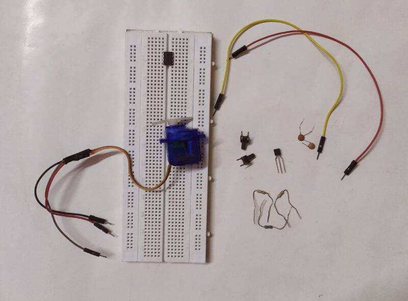
Components Required
| 555 Timer IC | |
| Servo motor | BUY LINK |
| 2. push buttons | BUY LINK |
| 9 volt battery | BUY LINK |
| BC547 trainsistor | BUY LINK |
| resistors 1K, 4.7K, 33K, 10K, 68K, | BUY LINK |
| capacitors0.1 uf | BUY LINK |
| Breadboard | BUY LINK |
| connecting wires | BUY LINK |
Circuit Diagram for Servo Motor Control
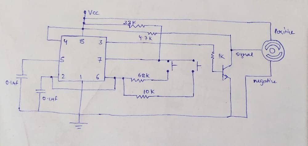
Place the 555 timer ic on the breadboard and connect pin 1 with the negative supply and pin 8 with the positive supply.
Connect pin 4 and 8 together. Take a 0.1 uF capacitor and connect its positive and negative legs with pin 5 and negative of supply.
Take another 0.1 uF capacitor with its positive and negative legs connected with pin 2 and negative of supply. Join pins 2 and 6 together.
Connect the base pin of the transistor with pin 3 via a 1K resistor. Join the emitter and collector legs with the negative and positive of the power supply.
Join the positive and negative wires of the servo motor with the power supply and the signal pin of the motor with the collector of the transistor. Connect pin 7 with the positive supply via a 33K resistor.
Now take two pushbuttons and place them on the breadboard. Join pin 6 with the one pair of interconnect pins of the pushbutton via 68K resistor and the other set of pins with pin 7 of the ic. Make the same connections for the other pushbutton just replace the 68K resistor with a 10K resistor.So, this is how the 555 timer control a servo motor.
Let’s test the Circuit

We hope that you liked this project and understand how we control the servo motor using a 555 timer ic. If you have any quarries related to the project then ask them in the comments section given below. Also, do check out tutorials on Arduino and Raspberry Pi written by us.
Thanks for reading.