

Table of Contents
Introduction
Hey geeks, welcome back Techatronic. In this article, we are going to make an Arduino LED project with a rotatory encoder and 16×2 LCD module. For your convenience, we are also providing the circuits and details of the connections for each and every configuration. A rotatory encoder has 5 pins, two of them are for power and three are for data. You can rotate it in both clockwise and anti-clockwise directions to control and select the Arduino with LED activity . So without wasting any more time let us make this Arduino LED project. You can also read our articles on IoT and basic electronics. Make the connections properly and then upload the given code to the Arduino.
Description
- For the first circuit i.e. the simple rotatory encoder project, when you rotate the knob of the rotatory encoder you can see the different values of the position variable in the Arduino serial monitor screen in this led with arduino activity.
- These values increase or decrease accordingly.
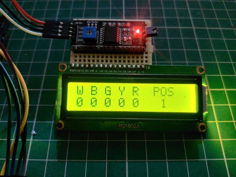
- Now for the second and third circuits, there is an LCD and LEDs connected with the arduino LED circuit .
- You can choose a specific LED by its position which can be seen on the LCD screen.
- in this led arduino project Just select the LED and push the knob of the rotatory encoder.
- If the respective LED was off then it will turn on and vice versa.
- 0 represents that the LED with Arduino is off and 1 denotes that it is on.
- When you rotate the knob of the rotatory encoder the position value increase or decreases and you can select the LED which you want to operate.
- You can also check the music reactive LED using Arduino made by us.

Components Required for arduino and LED

| Arduino UNO | BUY LINK |
| 16×2 LCD | BUY LINK |
| I2C module | BUY LINK |
| Breadboard | BUY LINK |
| jumper wires | BUY LINK |
| LEDs of different colors | BUY LINK |
| Rotatory Encoder | BUY LINK |
| USB cable for uploading the code | BUY LINK |

Circuit for Arduino with LED Project
NOTE: Please upload the code to the Arduino for which you make the circuit. Also, install <LiquidCrystal_I2C.h>, <Wire.h>, < LiquidCrystal.h> libraries in the Arduino IDE. Check here if you don’t know how to add a zip library in the Arduino IDE software.
Circuit for Rotatory Encoder With Arduino

- First, we have to connect the VCC pin of the rotatory encoder with Arduino 5v pin.
- After that join the GND pin of the rotatory encoder with the GND pin of the Arduino.
- Attach the CLK and DT pins of the rotatory encoder with the digital-2 and digital-4 pins of the Arduino.
- At last, connect the SW pin of the rotatory encoder with the digital-3 pin of the Arduino.
- Your circuit is complete now, please upload the code which is given below.
Code:
// TECHATRONIC.COM

 int counter = 0;
 int aState;
 int aLastState;
 const int RotaryCLK = 2; //CLK pin on the rotary encoder
 const int RotaryDT = 4; //DT pin on the rotary encoder
 const int RotarySW = 3; //SW pin on the rotary encoder
 void setup()
 {
   pinMode (RotaryCLK,INPUT); // CLK PIN OF ROTATRY ENCODER
   pinMode (RotaryDT,INPUT); // DT PIN OF ROTATRY ENCODER

   Serial.begin (9600);
   // Reads the initial state of the 2
   aLastState = digitalRead(RotaryCLK);
 }
 void loop()
 {
   aState = digitalRead(RotaryCLK); // Reads the "current" state of the outputA
   // If the previous and the current state of the 2 are different, that means a Pulse has occured
   if (aState != aLastState){
     // If the outputB state is different to the 2 state, that means the encoder is rotating clockwise

     if (digitalRead(RotaryDT) != aState) {
       counter ++;
     } else {
       counter --;
     }
     Serial.print("Position: ");
     Serial.println(counter);
   }
   aLastState = aState; // Updates the previous state of the 2 with the current state
 }
Circuit Without I2C Module

- In this circuit, we are making the project without using an I2C module.
- So first, make the connections between the pins of the 16×2 LCD and analog pins of the Arduino as shown in the diagram.
- You can also view the connections or Arduino with LED in our article on the interfacing of 16×2 LCD with Arduino.
- Then take 5 LEDs of different colors and join their negative legs with the GND pin of the Arduino via a 220 ohm resistor.
- Attach the positive leg of the red LED with the digital-10 pin of the Arduino.
- similarly, join the positive leg of yellow, green, blue, and white LEDs with the digital-9, digital-8, digital-7, digital-6 pins of the Arduino.
- After that connect the VCC pin of the rotatory encoder with the 5 volts pin of the Arduino.
- Join the GND pin of the rotatory encoder with the GND pin of the Arduino.
- Connect the CLK and DT pins of the rotatory encoder with the digital-2 and digital-4 pins of the Arduino.
- Attach the SW pin of the rotatory encoder with the digital-3 pin of the Arduino.
- Your circuit is complete now, please upload the code which is given below.
Code:
// TECHATRONIC.COM
#include "LiquidCrystal.h"
LiquidCrystal lcd(A0, A1, A2, A3, A4, A5);
// RS=A0, E=A1, D4=A2, D5=A3, D6=A4, D7=A5
const int RotaryCLK = 2; //CLK pin on the rotary encoder
const int RotaryDT = 4; //DT pin on the rotary encoder
const int RotarySW = 3; //SW pin on the rotary encoder (Button function)
int ButtonCounter = 0; //counts the button clicks
int RotateCounter = 0; //counts the rotation clicks
bool rotated = true; //info of the rotation
bool ButtonPressed = false; //info of the button
int CLKNow;
int CLKPrevious;
int DTNow;
int DTPrevious;
float TimeNow1;
float TimeNow2;
const int whiteLED = 6;
const int blueLED = 7;
const int greenLED = 8;
const int yellowLED = 9;
const int redLED = 10;
bool whiteLEDStatus = false;
bool blueLEDStatus = false;
bool greenLEDStatus = false;
bool yellowLEDStatus = false;
bool redLEDStatus = false;
void setup()
{
Serial.begin(9600);
lcd.begin(16,2);
lcd.setCursor(0,0); //Defining position to write from first row, first column .
lcd.print("W B G Y R POS");
lcd.setCursor(0,1); //second line, 1st block
lcd.print("0 0 0 0 0 0"); //You can write 16 Characters per line .
delay(3000); //wait 3 sec
pinMode(2, INPUT_PULLUP);
pinMode(3, INPUT_PULLUP);
pinMode(4, INPUT_PULLUP);
pinMode(whiteLED, OUTPUT); //white LED
pinMode(blueLED, OUTPUT); //blue LED
pinMode(greenLED, OUTPUT); //green LED
pinMode(yellowLED, OUTPUT); //yellow LED
pinMode(redLED, OUTPUT); //red LED
digitalWrite(whiteLED, LOW);
digitalWrite(blueLED, LOW);
digitalWrite(greenLED, LOW);
digitalWrite(yellowLED, LOW);
digitalWrite(redLED, LOW);
CLKPrevious = digitalRead(RotaryCLK);
DTPrevious = digitalRead(RotaryDT);
attachInterrupt(digitalPinToInterrupt(RotaryCLK), rotate, CHANGE);
attachInterrupt(digitalPinToInterrupt(RotarySW), buttonPressed, FALLING); //either falling or rising but never "change".
TimeNow1 = millis(); //Start timer 1
}
void loop()
{
printLCD();
ButtonChecker();
}
void buttonPressed()
{
//This timer is a "software debounce". It is not the most effective solution, but it works
TimeNow2 = millis();
if(TimeNow2 - TimeNow1 > 500)
{
ButtonPressed = true;
}
TimeNow1 = millis(); //"reset" timer; the next 500 ms is counted from this moment
}
void rotate()
{
CLKNow = digitalRead(RotaryCLK); //Read the state of the CLK pin
// If last and current state of CLK are different, then a pulse occurred
if (CLKNow != CLKPrevious && CLKNow == 1)
{
// If the DT state is different than the CLK state then
// the encoder is rotating CCW so increase
if (digitalRead(RotaryDT) != CLKNow)
{
RotateCounter++;
if(RotateCounter > 4)
{
RotateCounter = 0;
}
}
else
{
RotateCounter--;
if(RotateCounter < 0)
{
RotateCounter = 4;
}
}
}
CLKPrevious = CLKNow; // Store last CLK state
rotated = true;
}
void printLCD()
{
if(rotated == true) //refresh the CLK
{
lcd.setCursor(12,1);
lcd.print(RotateCounter);
Serial.println(RotateCounter);
rotated = false;
}
}
void ButtonChecker() //this is basically the menu part. keep track of the buttonpressed and rotatecounter for navigation
{
if(ButtonPressed == true)
{
switch(RotateCounter)
{
case 0:
if(whiteLEDStatus == false)
{
whiteLEDStatus = true;
digitalWrite(whiteLED, HIGH); //white LED is turned ON
}
else
{
whiteLEDStatus = false;
digitalWrite(whiteLED, LOW); //white LED is turned OFF
}
lcd.setCursor(0,1); // Defining positon to write from second row, first column .
lcd.print(whiteLEDStatus);
Serial.println(whiteLEDStatus);
break;
case 1:
if(blueLEDStatus == false)
{
blueLEDStatus = true;
digitalWrite(blueLED, HIGH);
}
else
{
blueLEDStatus = false;
digitalWrite(blueLED, LOW);
}
lcd.setCursor(2,1); // Defining positon to write from second row, first column .
lcd.print(blueLEDStatus);
break;
case 2:
if(greenLEDStatus == false)
{
greenLEDStatus = true;
digitalWrite(greenLED, HIGH);
}
else
{
greenLEDStatus = false;
digitalWrite(greenLED, LOW);
}
lcd.setCursor(4,1); // Defining positon to write from second row, first column .
lcd.print(greenLEDStatus);
break;
case 3:
if(yellowLEDStatus == false)
{
yellowLEDStatus = true;
digitalWrite(yellowLED, HIGH);
}
else
{
yellowLEDStatus = false;
digitalWrite(yellowLED, LOW);
}
lcd.setCursor(6,1); // Defining positon to write from second row, first column .
lcd.print(yellowLEDStatus);
break;
case 4:
if(redLEDStatus == false)
{
redLEDStatus = true;
digitalWrite(redLED, HIGH);
}
else
{
redLEDStatus = false;
digitalWrite(redLED, LOW);
}
lcd.setCursor(8,1); // Defining positon to write from second row, first column .
lcd.print(redLEDStatus);
break;
}
}
ButtonPressed = false; //reset this variable
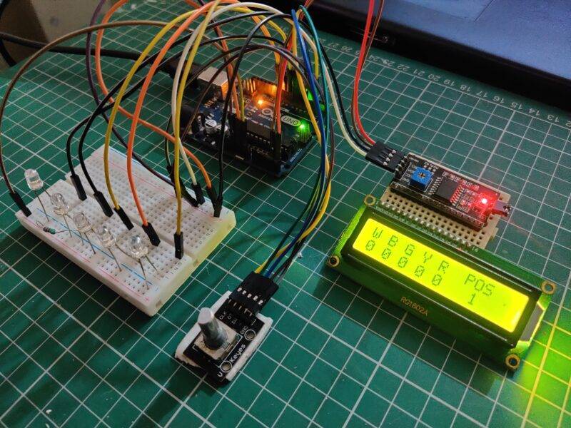
}Circuit with I2C module

- In this circuit, we are making the project using an I2C module.
- Connect the VCC pin of the I2C module with the 5 volts pin of the Arduino and the GND pin of the I2C module with the GND pin of the Arduino.
- Then join the SDA pin of the module with the analog-4 pin of the Arduino.
- Attach the SCL pin of the module with the analog-5 pin of the Arduino.
- Then make the connections between the pins of the 16×2 LCD and I2C module as shown in the diagram.
- Take LEDs of 5 different colors and join their negative legs with the GND pin of the Arduino via a 220 ohm resistor.
- Connect the positive leg of the red LED with the digital-10 pin of the Arduino. In the same way, join the positive leg of yellow, green, blue, and white LEDs with the digital-9, digital-8, digital-7, digital-6 pins of the Arduino.
- After that connect the VCC pin of the rotatory encoder with the 5 volts pin of the Arduino.
- Connect the GND pin of the rotatory encoder with the GND pin of the Arduino.
- Then attach the CLK and DT pins of the rotatory encoder with the digital-2 and digital-4 pins of the Arduino. Attach the SW pin of the rotatory encoder with the digital-3 pin of the Arduino.
- Your circuit is complete now, please upload the code which is given below.
Code:
// TECHATRONIC.COM
// I2C LIBRARY
//https://github.com/fdebrabander/Arduino-LiquidCrystal-I2C-library

#include <Wire.h>
#include <LiquidCrystal_I2C.h>
LiquidCrystal_I2C lcd(0x3F,16,2);
// SDA = A4
// SCL = A5

const int RotaryCLK = 2; //CLK pin on the rotary encoder
const int RotaryDT = 4; //DT pin on the rotary encoder
const int RotarySW = 3; //SW pin on the rotary encoder (Button function)
int ButtonCounter = 0; //counts the button clicks
int RotateCounter = 0; //counts the rotation clicks
bool rotated = true; //info of the rotation
bool ButtonPressed = false; //info of the button
int CLKNow;
int CLKPrevious;
int DTNow;
int DTPrevious;
float TimeNow1;
float TimeNow2;

const int whiteLED = 6;
const int blueLED = 7;
const int greenLED = 8;
const int yellowLED = 9;
const int redLED = 10;

bool whiteLEDStatus = false;
bool blueLEDStatus = false;
bool greenLEDStatus = false;
bool yellowLEDStatus = false;
bool redLEDStatus = false;

void setup()
{
 Serial.begin(9600);
  lcd.init();    // Arduino
 // lcd.begin();     // nodemcu
  lcd.backlight();
  lcd.setCursor(0,0); //Defining position to write from first row, first column .
  lcd.print("W B G Y R  POS");
  lcd.setCursor(0,1); //second line, 1st block
  lcd.print("0 0 0 0 0   0"); //You can write 16 Characters per line .
  delay(3000); //wait 3 sec
   pinMode(2, INPUT_PULLUP);
   pinMode(3, INPUT_PULLUP);
   pinMode(4, INPUT_PULLUP);
   pinMode(whiteLED, OUTPUT); //white LED
   pinMode(blueLED, OUTPUT); //blue LED
   pinMode(greenLED, OUTPUT); //green LED
   pinMode(yellowLED, OUTPUT); //yellow LED
   pinMode(redLED, OUTPUT); //red LED
   digitalWrite(whiteLED, LOW);
   digitalWrite(blueLED, LOW);
   digitalWrite(greenLED, LOW);
   digitalWrite(yellowLED, LOW);
   digitalWrite(redLED, LOW);

  CLKPrevious = digitalRead(RotaryCLK);
  DTPrevious = digitalRead(RotaryDT);

  attachInterrupt(digitalPinToInterrupt(RotaryCLK), rotate, CHANGE);
  attachInterrupt(digitalPinToInterrupt(RotarySW), buttonPressed, FALLING); //either falling or rising but never "change".

  TimeNow1 = millis(); //Start timer 1
}


void loop()
{
  printLCD();
  ButtonChecker();
}

void buttonPressed()
{
  //This timer is a "software debounce". It is not the most effective solution, but it works
  TimeNow2 = millis();
  if(TimeNow2 - TimeNow1 > 500)
  {
    ButtonPressed = true;
  }
  TimeNow1 = millis();  //"reset" timer; the next 500 ms is counted from this moment
}

void rotate()
{
  CLKNow = digitalRead(RotaryCLK); //Read the state of the CLK pin

  // If last and current state of CLK are different, then a pulse occurred
    if (CLKNow != CLKPrevious  && CLKNow == 1)
    {
    // If the DT state is different than the CLK state then
    // the encoder is rotating CCW so increase
      if (digitalRead(RotaryDT) != CLKNow)
      {
      RotateCounter++;

      if(RotateCounter > 4)
      {
       RotateCounter = 0;
      }

      }
      else
      {
      RotateCounter--;

      if(RotateCounter < 0)
      {
        RotateCounter = 4;
      }

      }
    }

  CLKPrevious = CLKNow;  // Store last CLK state
  rotated = true;
}


void printLCD()
{
    if(rotated == true) //refresh the CLK
    {
      lcd.setCursor(12,1);
      lcd.print(RotateCounter);
      Serial.println(RotateCounter);
      rotated = false;
    }

}


void ButtonChecker() //this is basically the menu part. keep track of the buttonpressed and rotatecounter for navigation
{
  if(ButtonPressed == true)
  {
    switch(RotateCounter)
    {
      case 0:
      if(whiteLEDStatus == false)
      {
        whiteLEDStatus = true;
        digitalWrite(whiteLED, HIGH); //white LED is turned ON
      }
      else
      {
        whiteLEDStatus = false;
        digitalWrite(whiteLED, LOW); //white LED is turned OFF
      }

      lcd.setCursor(0,1); // Defining positon to write from second row, first column .
      lcd.print(whiteLEDStatus);
      Serial.println(whiteLEDStatus);

      break;

      case 1:
      if(blueLEDStatus == false)
      {
        blueLEDStatus = true;
        digitalWrite(blueLED, HIGH);

      }
      else
      {
        blueLEDStatus = false;
        digitalWrite(blueLED, LOW);
      }

      lcd.setCursor(2,1); // Defining positon to write from second row, first column .
      lcd.print(blueLEDStatus);
      break;

      case 2:
      if(greenLEDStatus == false)
      {
        greenLEDStatus = true;
        digitalWrite(greenLED, HIGH);

      }
      else
      {
        greenLEDStatus = false;
        digitalWrite(greenLED, LOW);
      }

      lcd.setCursor(4,1); // Defining positon to write from second row, first column .
      lcd.print(greenLEDStatus);
      break;

      case 3:
      if(yellowLEDStatus == false)
      {
        yellowLEDStatus = true;
        digitalWrite(yellowLED, HIGH);
      }
      else
      {
        yellowLEDStatus = false;
        digitalWrite(yellowLED, LOW);
      }
      lcd.setCursor(6,1); // Defining positon to write from second row, first column .
      lcd.print(yellowLEDStatus);

      break;

      case 4:
      if(redLEDStatus == false)
      {
        redLEDStatus = true;
        digitalWrite(redLED, HIGH);

      }
      else
      {
        redLEDStatus = false;
        digitalWrite(redLED, LOW);
      }

      lcd.setCursor(8,1); // Defining positon to write from second row, first column .
      lcd.print(redLEDStatus);
      break;
    }
  }
  ButtonPressed = false; //reset this variable
}
About the Code
First, we define a counter variable and initialize it with a 0 value. Then we define three pins of the rotatory encoder. In the loop function, we are checking for the rotation made by the rotatory encoder and print the value of the position variable. In the case of LEDs, we are also checking if the user presses the button or not. If the user presses the button on a specific position then the respective device will go on/off as per the present conditions.

We hope that you liked this project and understand it’s working as well. If you have any doubts related to it then feel free to ask them in the comments section. Also, do check out more articles on Arduino and Raspberry Pi published by us.
Happy Learning!
Some latest arduino project
Rotatory Encoder Module With Arduino