

Hello geeks, welcome back to Techatronic. In this article, we are going to explain how a Rotatory Encoder module works with Arduino. You can make this project on your own by simply following the given procedure. If you are new to this field and want to explore more such amazing projects based on Arduino then please check out our articles once. We use an Arduino UNO and a KY-040 Rotatory encoder module in this project. Basically, Arduino is a microcontroller that uses IC ATmega328p for its functioning. The rotatory encoder we use in this project has a total of five pins, two of them are for power and the remaining three for the outputs. You have to complete the circuit first and then upload the given Arduino code.

How Does it Work?
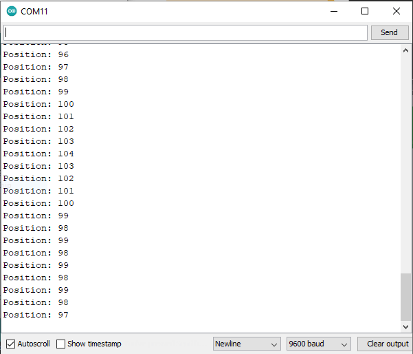
A rotatory encoder is a type of position sensor which is used to determine the angular position of a rotating shaft. It generates electrical signals according to the movement of the shaft. The CLK and DT pins are the output pins that generate two output signals. The Arduino read these two output signals to display the value of the position variable on the serial monitor. If we rotate the shaft then the values of these two outputs are different and by comparing them the value of the counter variable can be incremented or decremented as mentioned in the given code. Now we have some value stored in the counter variable so we can print it on the serial monitor screen. After printing the position, we have to update the value of the aLastState variable with the current state. When you start rotating the shaft of the rotatory encoder the values start changing on the Arduino serial monitor screen.

Components Required
| Arduino UNO | BUY LINK |
| USB cable for uploading the code | BUY LINK |
| KY-040 Rotatory encoder module | BUY LINK |
| Jumper wires | BUY LINK |

Circuit Diagram for the Project

| Arduino UNO | Rotary Encoder |
| ( +5V ) | + Positive |
| GND | GND |
| SW Pin | |
| 7 Pin | DT Pin |
| 6 Pin | CLK Pin |

You have to make the connections according to the given circuit diagram. Connect the 5-volt pin of the Arduino to the VCC pin of the rotatory encoder and the GND pin of the Arduino to the GND pin of the rotatory encoder. Attach the CLK and DT pins of the rotatory encoder to the digital-6 and digital-7 pins of the Arduino as shown in the image. Leave the SW pin of the rotatory encoder as it is. You can use DC batteries or a USB cable to power the Arduino. Once the Arduino starts working, you have to rotate the knob of the rotatory encoder module in a clockwise or counterclockwise direction to obtain different readings on the serial monitor screen.
Code for the Project
NOTE: Please upload the code which is given below as it is. After uploading, open the Arduino serial monitor for results.
// TECHATRONIC.COM

 int counter = 0;
 int aState;
 int aLastState;
 void setup()
 {
   pinMode (6,INPUT); // CLK PIN OF ROTATRY ENCODER
   pinMode (7,INPUT); // DT PIN OF ROTATRY ENCODER

   Serial.begin (9600);
   // Reads the initial state of the 6
   aLastState = digitalRead(6);
 }
 void loop()
 {
   aState = digitalRead(6); // Reads the "current" state of the outputA
   // If the previous and the current state of the 6 are different, that means a Pulse has occured
   if (aState != aLastState){
     // If the outputB state is different to the 6 state, that means the encoder is rotating clockwise

     if (digitalRead(7) != aState) {
       counter ++;
     } else {
       counter --;
     }
     Serial.print("Position: ");
     Serial.println(counter);
   }
   aLastState = aState; // Updates the previous state of the 6 with the current state
 }

Thanks for reading, we hope that you understand the project well. If you are facing any error while making this, do inform us in the comments section below. Check more Tutorials on Arduino and Raspberry pi.
HAPPY LEARNING!