
Hey Geeks, welcome back to Techatronic. In this article, we are going to discuss how you can make your own Arduino Vibration Detector Using SW 420 Vibration Sensor. You can also check out more such cool projects on Arduino. There are many Arduino boards available at your near and on the web, but we use the Arduino UNO board for making this project. Basically, Arduino is a microcontroller that uses a 40 pin IC, ATmega 328p for its functioning. For alerting the surroundings we use a Buzzer in this project which stops beeping when the vibration sensor detects the vibration. We also use a red and green LED which glows according to the detection of the vibration. you can also check out our articles on Basic Electronics. You have to complete the circuit and then upload the Arduino code which is given below. For such amazing projects, you can also check out our Ebook on Arduino and easily learn to make your own projects.
How Does it Work?
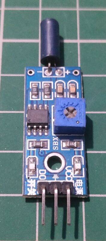
I hope you are familiar with the working of the SW 420 Vibration sensor, if not don’t worry we will explain it here. Basically, it is a sensor that generates its output according to the vibration detected by it. Whenever the sensor detects a little or large vibration it generates a high output signal otherwise a low output signal. In this project, we use an SW 420 vibration sensor with Arduino to make a Vibration detector. When the vibration sensor doesn’t detect any vibration signals then at that time green LED will glow and the buzzer will ring and when the vibration sensor detects any vibration signal then the red LED will glow. The LEDs and the buzzer is controlled via Arduino according to the output signals provides by the vibration sensor.
Components Required
- Arduino UNO
- USB Cable for Uploading the Code
- Jumper Wires
- SW 420 Vibration Sensor
- 220-ohm Resistors
- Buzzer
- Red and Green LED

Circuit Diagram of the Project

| Arduino UNO | Vibration Sensor | ||
| ( +5V ) | VCC | ||
| GND | GND | ||
| D4 Pin | DO | ||
| Arduino UNO | Buzzer | ||
| D7 Pin | Positive Terminal | ||
| GND | Negative Terminal | ||
| Arduino | LED G | LED R | 220 Ohm Resistor |
| D5 Pin | Anode Pin | ||
| D6 Pin | Anode Pin | ||
| Cathode Pin | Cathode Pin | Terminal 1 |
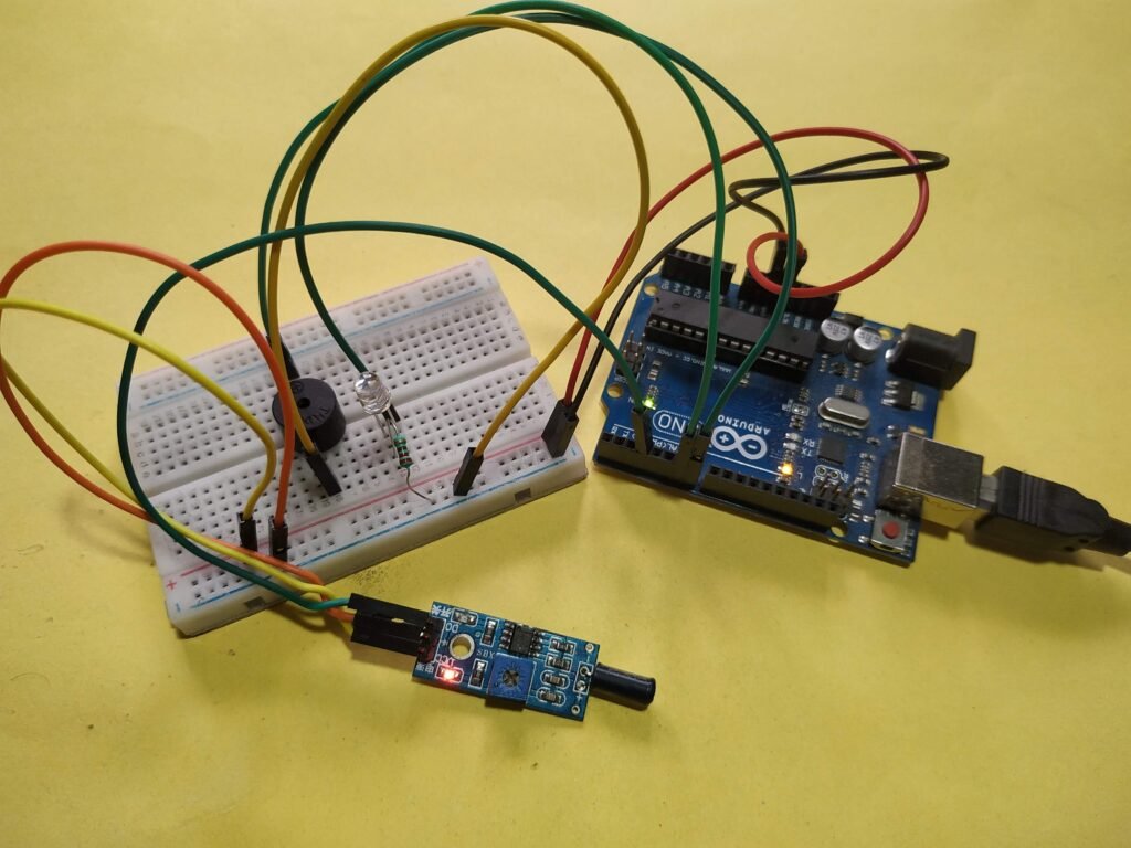
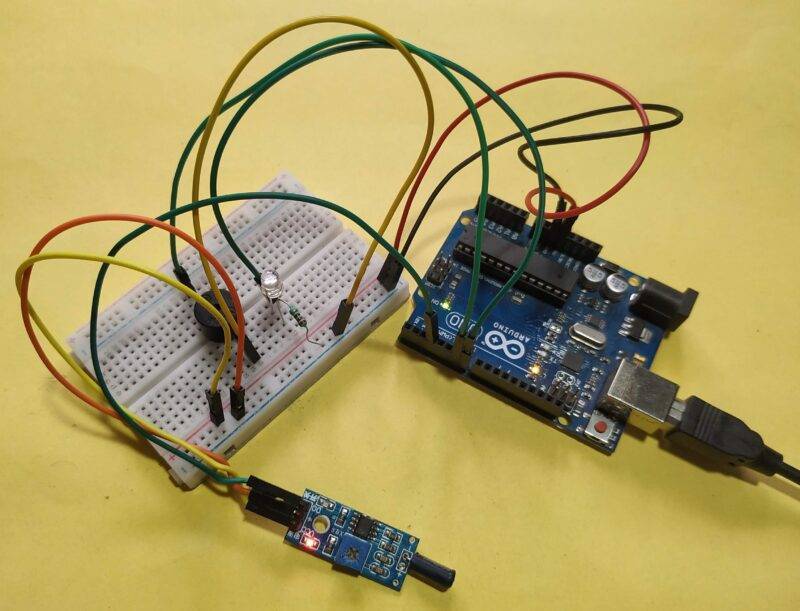
You have to make the connections according to the diagram given above. You can power the Arduino either by a USB cable or by a 9-volt battery. Connect the 5-volt pin of the Arduino to the VCC pin of the vibration sensor and the GND pin of the Arduino to the GND pin of the vibration sensor. Now connect the OUT pin of the vibration sensor to the digital 4 pin of the Arduino. Attach the positive wire of the buzzer to the digital 7 pins of the Arduino and the negative wire to the GND pin of the Arduino. Use breadboard to combine the negative wires of both the LEDs and then join it with the GND pin of the Arduino through a 220-ohm resistor. Connect the positive wire of the red LED to the digital 6 pin and the positive wire of the green LED to the digital 5 pins of the Arduino. Your circuit is complete, now upload the code given below to the Arduino.
Code for the Project
NOTE: Upload the code given below to the Arduino.
 // Techatronic.com
 int val = 0 ;
 void setup()
 {
 Serial.begin(9600);
 pinMode(4,INPUT); // pir sensor output pin connected
 pinMode(5,OUTPUT); // Green led pin
 pinMode(6,OUTPUT); // Red led pin
 pinMode(7,OUTPUT); // Buzzer pin
 }
 void loop()
 {
 val = digitalRead(4); // pir sensor output pin connected
 Serial.println(val); // see the value in serial monitor in Arduino IDE
 delay(100);
 if(val == 0 )
 {
 digitalWrite(5,HIGH);  // Green led on
 digitalWrite(6,LOW);  // Red led off
 digitalWrite(7,HIGH); // Buzzer on
 }
 else
 {
 digitalWrite(5,LOW);  // Green led off
 digitalWrite(6,HIGH); // Red led on
 digitalWrite(7,LOW); // Buzzer off
 }
 }
Hope you understand the project well and if you are facing any errors please do inform us in the comments section below. You can also check out more Arduino Tutorials.
HAPPY LEARNING!