

We all have sure observed that our phone display turns off during phone calls when we put it near our ears. So, do you ever wonder how does this happen??? IR sensor with Arduino and display makes the Obstacle detector.
It is not a hi-tech thing but a simple IR sensor to detect the obstacle near the phone we are also making the same project in this article with an IR sensor with Arduino. Also, many other devices like toy helicopters which fly if we put our hand under them, or any drones that can fly and land automatically.
All these devices use IR sensor with Arduino to detect obstacles or short distances.
Many other versions of ir distance sensor Arduino and kits are available in the market for a good price but we are here to encourage you all to DIY yourself the simple things with the help of basic components like Arduino, led, buzzer, and a few others.

How to make an Obstacle Detector By IR Sensor with Arduino: –
Components used in this are as always very basic ones, an Arduino Uno or any
another microcontroller you have, an LED, a buzzer, and a few others.
There are basic, good, and also arrays of IR sensors available in the market for various purposes but
the use and working of each are the same the difference in array in simple one it that in
the array you get the average value of 4 to 5 IR sensors to get a more error-free value,
this we’ll discuss some other day in the future but today let’s switch over to our topic
i.e., IR SENSOR with Arduino.
So as before it is the most common sensor among beginners and
very interesting projects can be designed using this like line follower robots,
Obstacle avoiding robots, and many others.
IR sensor contains two LEDs one is white which is an Infrared Light transmitter and another one is Black which is an Infrared Light receiver.
As the name suggests their work is so obvious. The sensor is built out of LM358 IC and is similar to LM393 IC which I think you all must be familiar with and know a bit about this IC.

The sensor also has an onboard power led and also an onboard Status led which will blink whenever the sensor detects or receives back the infrared light emitted by the infrared emitter.
The sensor gives both digital and analog output.
The difference between the two is very simple in digital output only high or low means either 1 or 0 is transmitted to a microcontroller but in the analog signal, a wide range of values from 0 to 1023 is
transmitted to the microcontroller which relates to the intensity of light received by the receiver.
You can also slightly trim the values of the IR sensor with Arduino with the help of a potentiometer provided on the sensor PCB.
*NOTE: – THE SENSOR VALUES DEPEND ON THE DISTANCE OF THE EMITTED LIGHT, REFLECTING SURFACE, AND RECEIVER. ALSO, BLACK
OR DARK SURFACE CAN ABSORB ALL THE LIGHT INCLUDING INFRARED SO THE SENSOR WON’T WORK ON THOSE SURFACES.
SCHEMATIC DIAGRAM/ IR Sensor with Arduino Circuit:-
- FEATURES AND APPLICATIONS IR Sensor with Arduino: –
The range is a short but appropriate value
Easy to use and fix
Adjustable value
Low price
Can be used in various distance or obstacle-related projects.
- SENSOR SPECIFICATIONS:
Components Required for IR Sensor with Arduino
- Arduino UNO
- USB cable for uploading the code
- IR sensor
- Buzzer and an LED
- Jumper wires and a breadboard
- 220-ohm resistor
-
IR SENSOR WITH ARDUINO CIRCUIT DIAGRAM:
Circuit diagram for digital output of IR Sensor with Arduino
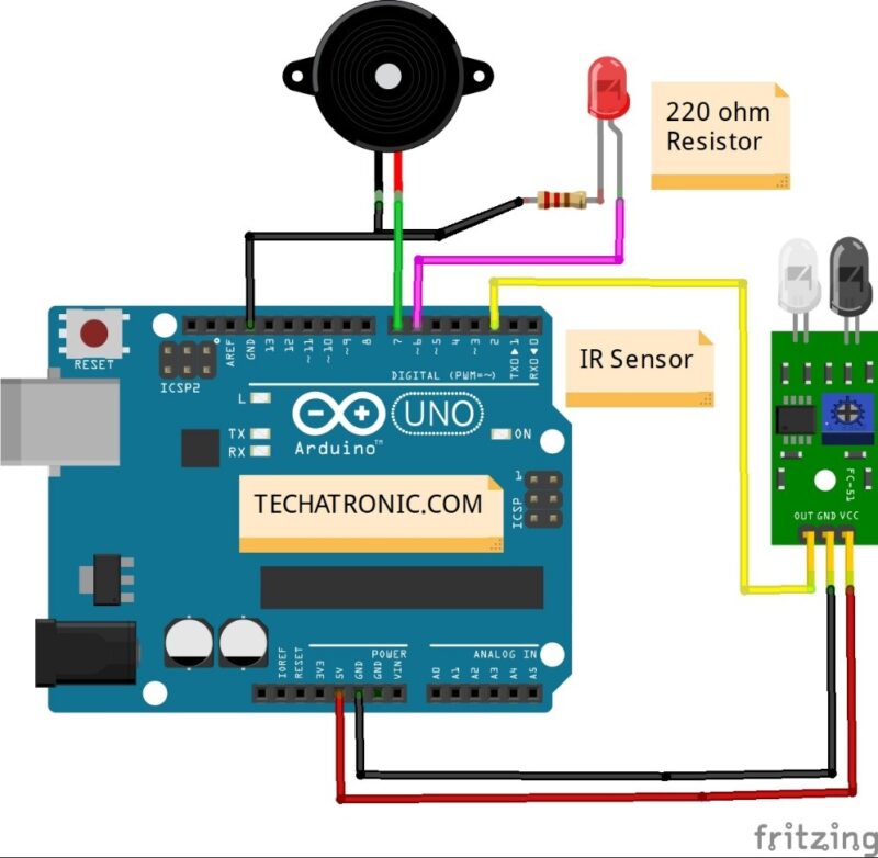
| Arduino UNO | IR Sensor | |
| ( +5V ) | VCC | |
| GND | GND | |
| D2 Pin | OUT Pin | |
| Arduino UNO | Buzzer | |
| D7 Pin | Positive | |
| GND | Negative | |
| Arduino | LED R | 220 Ohm Resistor |
| D6 Pin | Anode Pin | |
| GND | Terminal 1 | |
| Cathode Pin | Terminal 2 |
Circuit diagram for analog output of IR Sensor with Arduino
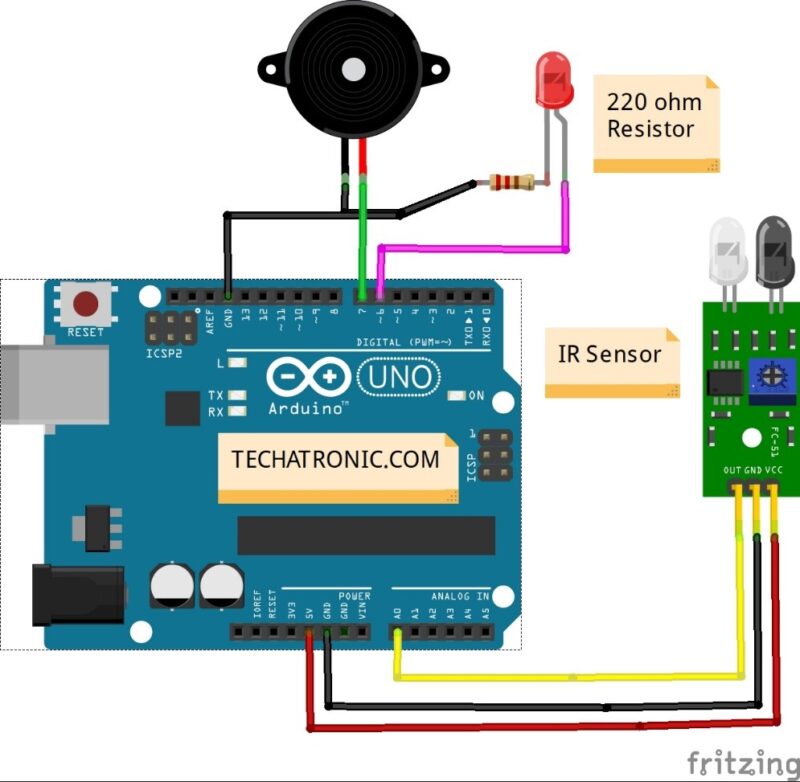
connection table for IR Sensor with Arduino
| Arduino UNO | IR Sensor | |
| ( +5V ) | VCC | |
| GND | GND | |
| D2 Pin | OUT Pin | |
| Arduino UNO | Buzzer | |
| A0 Pin | Positive | |
| GND | Negative | |
| Arduino | LED R | 220 Ohm Resistor |
| D6 Pin | Anode Pin | |
| GND | Terminal 1 | |
| Cathode Pin | Terminal 2 |
the above-given circuit diagram is only for the LED notification. when the IR Sensor with Arduino detects anything it will notify by the LED. the next image is for the Sound notification we will use the buzzer in that circuit.
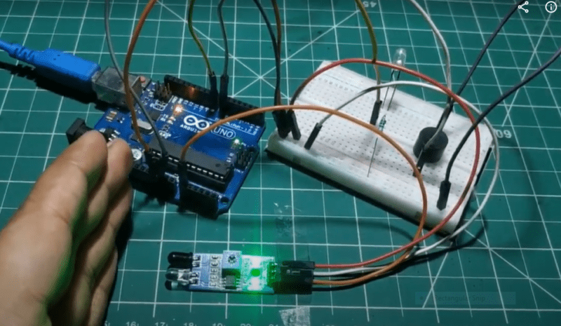
First, take the power lines onto the breadboard from the microcontroller
VCC/5v–>+ line and GND–> – line.
Then connect the sensor to the breadboard and connect power to the sensor from powerlines using jumper wires.
Now connect the D0 PIN OF SENSOR TO MICROCONTROLLER DIGITAL PIN 2.
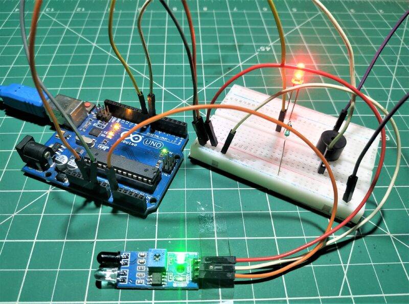
Now connect LED to the breadboard + to digital pin 13 of Arduino and – to and in series with 220-ohm resistor. Moreover, we can also use it in analog mode by that simply connecting the A0 pin of the sensor to pin A0 of the microcontroller. Enhance this version by adding a buzzer to it also like in the above diagram. Connect -live of the buzzer to GND on a breadboard, and +tive to 5V on a breadboard.
IR Sensor with Arduino Code:-
 // IR Sensor with Arduino
//put this code in the ide of arduino from this line ( FOR digital output)
 //Digital code
 // Techatronic.com
 int val = 0 ;
 void setup()
 {
 Serial.begin(9600); // sensor buart rate
 pinMode(2,INPUT);  // IR sensor output pin connected
 pinMode(6,OUTPUT);  // LED
 pinMode(7,OUTPUT);  // BUZZER
 }
 void loop()
 {
 val = digitalRead(2);  //  IR sensor output pin connected
 Serial.println(val);  // see the value in serial monitor in Arduino IDE
 delay(500);
 if(val == 1 )
 {
 digitalWrite(6,HIGH);  // LED ON
 digitalWrite(7,HIGH);  // BUZZER ON
 }
 else
 {
 digitalWrite(6,LOW);  // LED OFF
 digitalWrite(7,LOW);  // BUZZER OFF
 }
 }
// ir sensor with arduino analog value
 // IR Sensor with Arduino
// Techatronic.com
 void setup()
 {
 Serial.begin(9600); // sensor baud rate
 pinMode(6,OUTPUT);  // LED
 pinMode(7,OUTPUT);  // BUZZER
 }
 void loop()
 {
 int s1=analogRead(A0); //ANALOG PIN FOR SENSOR
 Serial.println(s1);   // see the value in serial monitor in Arduino IDE
 delay(100);
 if(s1>200 )
 {
 digitalWrite(6,HIGH);  // LED ON
 digitalWrite(7,HIGH);  // BUZZER ON
 }
 else
 {
 digitalWrite(6,LOW);  // LED OFF
 digitalWrite(7,LOW);  // BUZZER OFF
 }
 }
WORKING of ir sensor with arduino : –
As the code in the setup section, we define the pin along with the type to which the sensor is connected also we initialize the pin and type for the led and buzzer.
In the loop section, we read the digital value on pin 2 of the microcontroller and according to the value, we apply conditions either 1 or 0 to turn the led and buzzer on or off.
In the analog code in the loop section, we read the analog value i.e., 0-1023 values on pin A0 and according to the value of 200 or more, we turn the led and buzzer on or off.
Related Project
IoT Projects for the final year – IR sensor Notification IoT