
Hey guys, welcome back to Techatronic. There are a lot of robots in robotics that students are interested to make. some of the robots are most popular like Obstacle avoiding robot and Line following robot Arduino which we are making today with all the detail. and step-by-step instructions. what do you need to make this? you need to know some basics of electronic and Arduino coding and connection. and if you are not aware of all these things you can learn them from our blog section. we have uploaded all the content there. here you will learn all the things required to make this awesome robot. if you read the full article carefully and follow all the steps then you will definitely learn and make it.

If you have made ever this kind of robot then this will be tough for you. maze solver robot is also similar to this. this project can use at many places like hotels and restaurants to serve the customers. This is your call where you want to use it. if you are planning to have this robot ready-made from the market it will be expensive but with this tutorial, you can make this robot cheap. line following robot Arduino can be made at a very low price nearly $20. which is quite cheap and can anyone easily afford it. and another benefit is that you can make another project Bluetooth RC car with the same kit only you have to buy a Bluetooth module.
What is a line follower robot?
The line follower robot is an automatic robot that can follow a single path which can be any color line. mainly we use black line and the white surface so that the sensor can easily get the difference between colors. line following robot is many types depend upon you which resources are available. you can make this robot only using the sensor and motor driver. but it may not accurate. that’s why we always prefer the Arduino line following robot. to make this robot maze solver you need to add some conditions to it like right dominated or left dominated. it looks like a small toy car so, some people called it to line the following car.
Why this Project?
No doubt this is a very cool and interesting project. This will help you to learn the Ir sensor interfacing, motor driver interfacing, and many more protocols and connections. after completing this project you have completed the following topics.
- Dc motor interfacing
- Motor driver usage
- Connections
- Circuit diagram analysis
- Coding fundamental
- Interface two IR sensor
more than 6 topics you will cover with this activity. what do you need to do? you need to follow all the steps and learn every single thing mention here. we are sharing all the required detail. if you have any query or problem you can also ask us in the comment section. There is no cost or anything hidden charge to learn all the topics. these all free of cost. you should learn. all the very best. Line following robot Arduino is the best controller to do this awesome project.
How Does the line following robot work?
let me first explain how should be the line. the line should be prepared carefully. no extra corners, no use of grey color, don’t make the pattern at the land. When we place the robot car at the line following the surface. the sensor of the car will detect the surface either white or black. if both sensors are on the black then the line follower will stop. and if both sensors are on the white surface then the robot will start to move.
line follower robot start run over the white surface at we placed our robot on the white chat paper. if any sensor will come near the black line. the robot will turn against the direction of the line. for example, if the car goes to the left then the robot will slide lightly in right. and the same for the other sensor. all the main work is done here by the sensor. the sensor detects the color and then the robot reacts accordingly.
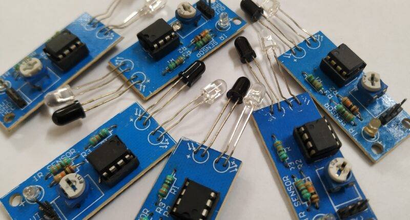
Ir sensor has an Infrared sensor that gives output according to the received light at the photosensor. at the black color, their sensor will send the 0 value. Arduino received this value then compare it with the given condition and send the instruction according to the database. Arduino collects data from both of the sensors at the same time and compares both sensor values with the previous. Arduino sends an instruction to the motor driver as the electrical signal with 3.3v amplitude which is less to drive the motor, now we have to connect the L298N driver with the Motor. because without the driver Arduino can’t rotate the motor. so here we are sharing all the detail.
Components Required:-
| Arduino uno | BUY LINK |
| 2-IR Sensor | BUY LINK |
| Chassis | BUY LINK |
| 4 wheel | BUY LINK |
| 4 bo motor | BUY LINK |
| jumper wire | BUY LINK |
| Battery 9v | BUY LINK |
| L298N MOTOR Driver | BUY LINK |
You can buy all components together-BUY LINK
line follower robot circuit diagram

| Arduino UNO | L298N Motor Driver | ||||
| 9 Pin | IN 1 | ||||
| 10 Pin | IN 2 | ||||
| 11 Pin | IN 3 | ||||
| 11 Pin | IN 4 | ||||
| Arduino UNO | IR Sensor 1 | IR Sensor 2 | |||
| ( +5V ) | + VCC | + VCC | |||
| GND | GND | GND | |||
| 8 Pin | OUT Pin | OUT Pin | |||
| Arduino UNO | 9 & 12 V Battery | Motor Driver | |||
| Positive | +12 Volt | ||||
| ( +5V ) | +5 Volt | ||||
| GND | Negative | GND | |||
| Arduino | Led R | Led G | Led B | Led Y | 220 Ohm Resistor |
| D5 Pin | Anode | ||||
| D6 Pin | Anode | ||||
| D7 Pin | Anode | ||||
| D8 Pin | Anode | ||||
| GND | Terminal 1 | ||||
| Cathode | Cathode | Cathode | Cathode | Terminal 2 | |
| Motor 1, 2 | Motor 3, 4 | L298N Motor Driver | |||
| Terminal 1 | Terminal 1 Output | ||||
| Terminal 2 | Terminal 2 Output | ||||
| Terminal 1 | Terminal 3 Output | ||||
| Terminal 2 | Terminal 4 Output |
line follower robot code
 // TECHATRONIC.COM
 int val = 0 ;
 int va2 = 0 ;
 void setup()
 {
   Serial.begin(9600); // sensor buart rate
   pinMode(2,INPUT);  // IR 1 SENSOR
   pinMode(3,INPUT);  // IR 2 SENSOR
   pinMode(5,OUTPUT); // LED PIN
   pinMode(6,OUTPUT); // LED PIN
   pinMode(7,OUTPUT); // LED PIN
   pinMode(8,OUTPUT); // LED PIN
   pinMode(9,OUTPUT);  // MOTOR 1 PIN
   pinMode(10,OUTPUT); // MOTOR 1 PIN
   pinMode(11,OUTPUT); // MOTOR 2 PIN
   pinMode(12,OUTPUT); // MOTOR 2 PIN
 }
 void loop()
 {
  val = digitalRead(2); // IR 1 sensor output pin connected
  va2 = digitalRead(3); // IR 2 sensor output pin connected
  Serial.println(val); // see the value in serial mpnitor in Arduino IDE
  Serial.println(va2); // see the value in serial mpnitor in Arduino IDE
  delay(10);
  if(val == 0 )       // RIGHT DIRECTION
  {
    digitalWrite(5,HIGH);  // LED ON
    digitalWrite(6,LOW);  // LED OFF
    digitalWrite(7,HIGH);  // LED ON
    digitalWrite(8,LOW);  // LED OFF
    digitalWrite(9,HIGH);  // MOTOR 1 HIGH
    digitalWrite(10,LOW);  // MOTOR 1 LOW
    digitalWrite(11,HIGH); // MOTOR 2 HIGH
    digitalWrite(12,LOW);  // MOTOR 2 LOW
  }
  if(va2 == 0 )       // LEFT DIRECTION
  {
    digitalWrite(5,LOW);  // LED OFF
    digitalWrite(6,HIGH);  // LED ON
    digitalWrite(7,LOW);  // LED OFF
    digitalWrite(8,HIGH);  // LED ON
    digitalWrite(9,LOW);  // MOTOR LOW
    digitalWrite(10,HIGH); // MOTOR HIGH
    digitalWrite(11,LOW);  // MOTOR LOW
    digitalWrite(12,HIGH); // MOTOR HIGH
  }
  if(val == 0 & va2 == 0 ) // FORWARD DIRECTION
  {
    digitalWrite(5,HIGH);  // LED ON
    digitalWrite(6,LOW);  // LED OFF
    digitalWrite(7,LOW);  // LED OFF
    digitalWrite(8,HIGH);  // LED ON
    digitalWrite(9,LOW);  // MOTOR 1 LOW
    digitalWrite(10,HIGH); // MOTOR 1 HIGH
    digitalWrite(11,HIGH); // MOTOR 2 HIGH
    digitalWrite(12,LOW);  // MOTOR 2 LOW
  }
   if(val == 1 & va2 == 1 ) // STOP DIRECTION
  {
    digitalWrite(5,LOW);  // LED OFF
    digitalWrite(6,LOW);  // LED OFF
    digitalWrite(7,LOW);  // LED OFF
    digitalWrite(8,LOW);  // LED OFF
    digitalWrite(9,LOW);  // MOTOR 1 LOW
    digitalWrite(10,LOW);  // MOTOR 1 LOW
    digitalWrite(11,LOW);  // MOTOR 1 LOW
    digitalWrite(12,LOW);  // MOTOR 1 LOW
  }
  }
Upload the given code into the Arduino. All the best guys.