
Introduction:-
Hey guys, Welcome back to Techatronic. Today we are going to make another activity with the Sound sensor. In the previous post, we learned how to interface dht11 with Arduino. I hope you have made it. but This sound sensor with Arduino activity is simple than the last activity. here you do not need to install any library or anything. you just simply make the connection and upload the code into the Arduino. we are going to share every information to make this basic activity. The sound sensor is better than a single mic to interface with the Arduino. or to make the projects. Once I have made a project with only mic and MOSFET but it was not that much accurate. So, now we are using this sound sensor with Arduino now and it is more accurate. all depend upon your code.
We almost uploaded all the sensors with Arduino in the Arduino Tutorial section. if you wanna learn Arduino without paying a penny then you can refer to this course. in case you didn’t get the sensor then you can connect Arduino with a microphone with a resistor in series. But we would prefer the sensor module always. you can order the sensor online too. this activity will help you to make the big project. such as music reactive light. or clop control switch. there you need to clap to switch on the light.
What is the Sound sensor?
A sound sensor is a module that can detect sound waves through their intensity and then it will convert the sound wave into an electrical signal. so you can read the electrical signal into the electronic device.
This is how the sound waves work in the environment. Sound waves travel in the air by the motion of air molecules. the air molecules move according to the sound wave. these air molecules incident on the sound sensor diaphragm. the sensor works the same as our ear diaphragm. the sound sensor gets the air molecules vibrations which are caused by the sound wave and then the sensor converts this vibration to the electrical signal. This makes more accuracy when the sound sensor with Arduino connects.
Sensor specification:
- compatible interface
- own plug and play system, no soldering or jumper wires needed for pairing as compared to other sound sensor breakout boards
- Analog output signal
- Wide supply voltage range: 4V-12V
- Low quiescent current drain: 4mA
- 2.0cm x 2.0cm twig module
- Minimum external parts

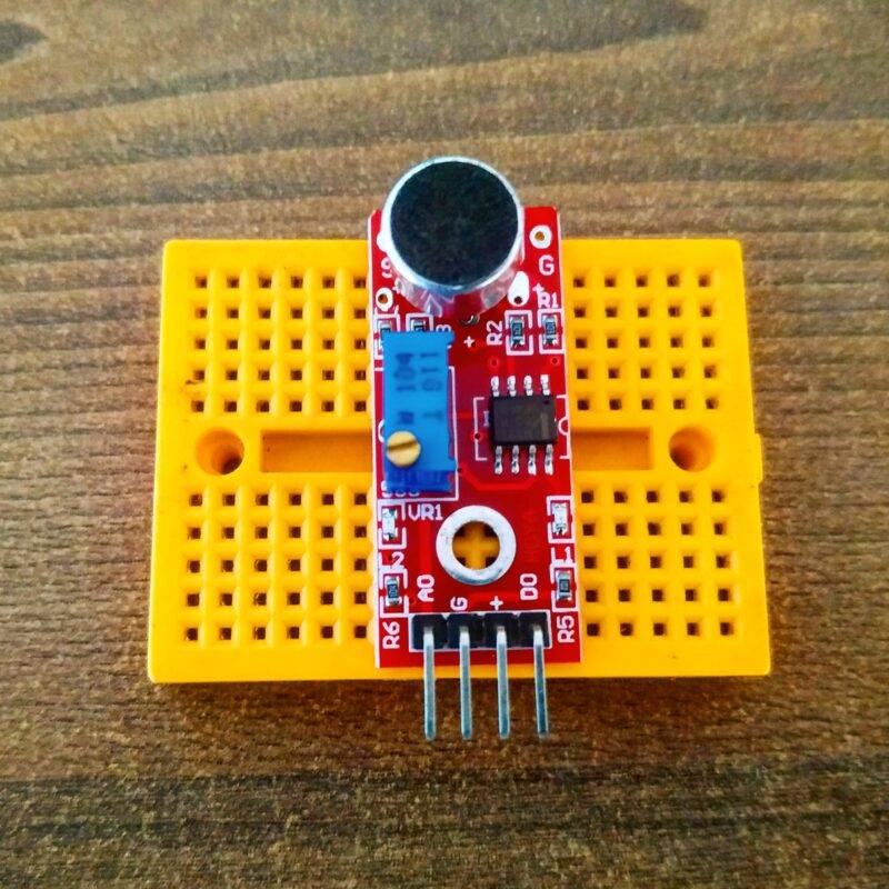
How does this work?
In the sensor, the microphone will get the sound wave in the form of air molecule vibrations. the diaphragm sends this converted electrical wave to the operational amplifier. here the amplifier is lm398 mostly used in the sound sensor. and there is a potentiometer that can adjust the sensitivity of the sensor. there are four pins at the sensor. Data pin, ground pin, D1, and A1 pin. from where you can get the analog as well as the digital data it depends on you how you are using the sensor.
If you are using the digital pin you do not need to open the serial monitor but if you are using analog you must know how to open the serial monitor and observe the serial monitor for the value. In analog, you can adjust the Arduino sound sensor sensitivity with the calibration.
how to observe the analog value in the serial monitor. first, you need to mention the serial monitor to begin in the code. and after uploading the code into the Arduino you need you open the serial monitor. and if you are not aware of the progress then you can prefer the below-given images.
Click on the upper right corner serial monitor logo.
then select the baud rate to 9600 and no line ending.
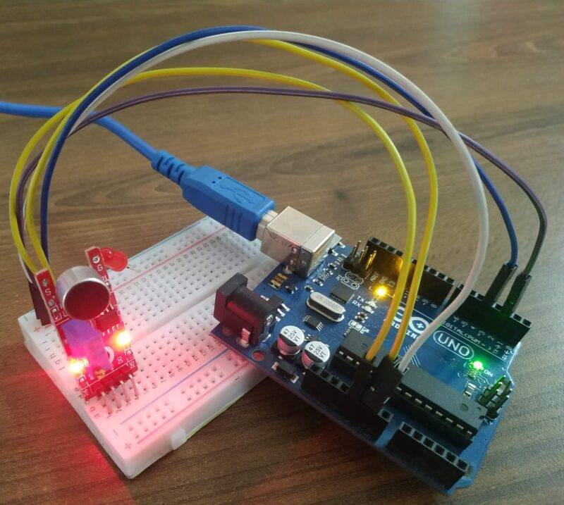
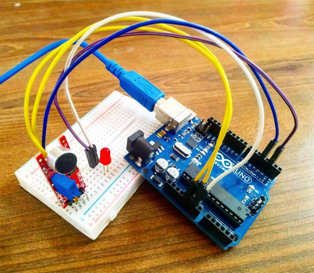
Components required Arduino with microphone sensor?
- Arduino Uno
- Sound sensor
- Breadboard
- jumper wire
- Arduino Cable USB type A to B

Sound sensor Arduino project circuit diagram(Digital Pin)
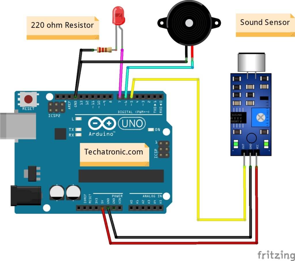
| Arduino UNO | Sound Sensor | |
| ( +5V ) | VCC | |
| GND | GND | |
| D5 Pin | OUT Pin | |
| Arduino UNO | Buzzer | |
| D6 Pin | Positive | |
| GND | Negative | |
| Arduino | LED R | 220 Ohm Resistor |
| D7 Pin | Anode Pin | |
| GND | Terminal 1 | |
| Cathode Pin | Terminal 2 |
Arduino code for sound sensor
 // Techatronic.com
 int val = 0 ;
 void setup()
 {
   Serial.begin(9600); // sensor buart rate
   pinMode(5,INPUT); // sound sensor
   pinMode(7,HIGH); // LED PIN
   pinMode(6,HIGH); // BUZZER PIN
 }
 void loop()
 {
  val = digitalRead(5); // pir sensor output pin connected
  Serial.println(val); // see the value in serial mpnitor in Arduino IDE
  delay(100);
  if(val == 0 )
  {
   digitalWrite(7,HIGH); // LED ON
   digitalWrite(6,LOW); // BUZZER ON
   delay(1000);
  }
  else
  {
   digitalWrite(6,HIGH); // LED OFF
   digitalWrite(7,LOW); // BUZZER OFF
  }
  }
the above code can only work with the digital circuit.
Circuit diagram for analog Pin

| Arduino UNO | Sound Sensor | |
| ( +5V ) VCC | VCC | |
| GND ( Ground ) | GND | |
| A0 Pin | OUT Pin | |
| Arduino UNO | Buzzer | |
| D6 Pin | Positive | |
| GND ( Ground ) | Negative | |
| Arduino | LED R | 220 Ohm Resistor |
| D7 Pin | Anode Pin | |
| GND | Terminal 1 | |
| Cathode Pin | Terminal 2 |
Sound sensor Arduino Code (Analog)
 // Techatronic.com
 void setup()
 {
   Serial.begin(9600);
   pinMode(7,OUTPUT); // Red led pin
   pinMode(6,OUTPUT); // Buzzer pin
 }
 void loop()
 {
  int s1=analogRead(A0);
  Serial.println(s1);
  delay(50);
  if(s1>100 )
  {
   digitalWrite(7,LOW);  // Red led off
   digitalWrite(6,HIGH); // Buzzer on
  }
   else
  {
   digitalWrite(7,HIGH); // Red led on
   digitalWrite(6,LOW); // Buzzer off
  }
 }
Upload the given code to the Arduino.