
Sound sensor is the most basic sensor to start with, It is mostly used among hobbyist and professionals. So, here we are going to make an descrition on How sound sensor works, and how can we use this sensor in out applications.
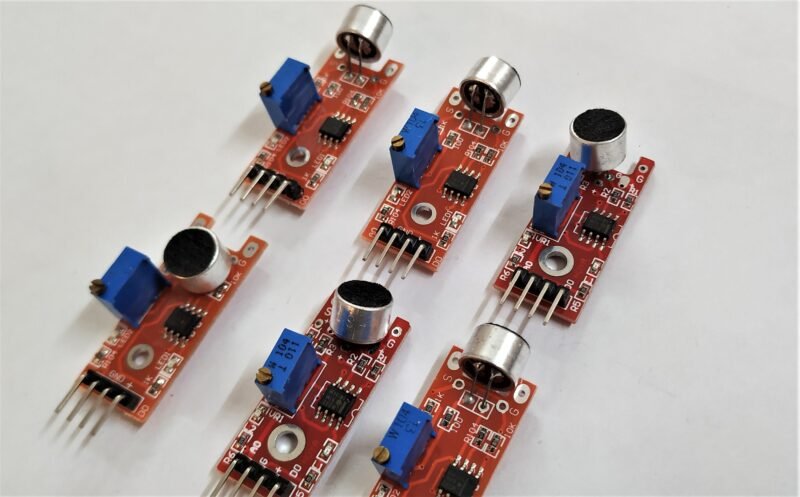
- This is very simple sensor and is easily available either in the online or offline market. Sound sensors come in various types and sizes. For projects based on sound sensor.
- The Sound sensor which I’m going to explain today is the very basic one. But I advise if you want to use sound sensor for more professional work, then use some better quality available in the market.
- This sensor which I’m demonstrating gives both types of output, but I generally prefer only digital output. As Analog output is not that good as Digital.
- Along with this, it also has an on-board led for status of the sound received. The schematic and the working according to that will be explained further.

Sound sensor Construction

- Above is the schematic of Sound sensor, which I’m going to explain today. This schematic might be different slightly. From the version available physically.
- The sensor is built out of the LM393N IC, which is a dual voltage comparator. This sensor works on the principal of voltage comparison like most of the other sensor which I have mentioned in basic electronics section.
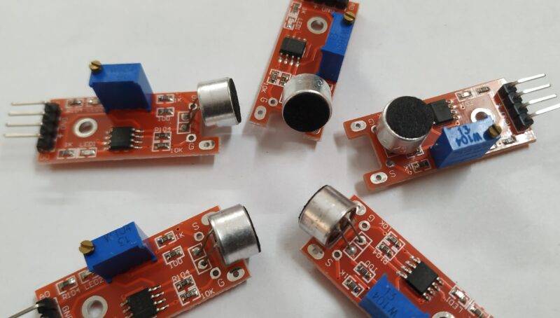
- The condenser microphone is used in this sensor, which is of quite good quality. But as I said earlier for professional work use some of better quality.
- The PCB of the sensor also has a potentiometer of 10 kΩ, which is used to trim the values which are sent to the microcontroller. Also, there is an onboard status LED indicator provided on the PCB
Working of sound sensor
- The working of this Sound detector is very similar to sensor which are built out of LM393 IC. The link to other sensors which are similar to it are also included in the basic electronic section.
- The inverting input of the one comparator is connected to the positive pin of the condenser microphone with a resistor of 150 Ω in series.
- The non-inverting input of both the comparators is connected to the voltage divider of 100 kΩ each between VCC & GND.
- The output of the first comparator is connected to the digital output and inverting input of the second comparator. The output of 2nd is connected to the VCC of the indicator LED with 10 kΩ in series.
- The potentiometer is connected to the inverting input of the first comparator with VCC. Also the analog input is connected to this pin also.

Advantages:
- The main advantage of the Sound sensor is the simplicity of the sensor, which makes it ideal sensor that can be use by the beginners for making a grip in this field.
- Secondly the condenser microphone it can be replaced in case of any damage also you can replace it with some high quality condenser microphone as per your need.
- Furthermore, sensor also give analog output which though is unstable yet still useful in some cases, like in making VU meter for DIY projects and stuff like this.
- The pull-up to the microphone input to the inverting input of the Op-Amp can be controlled with the potentiometer, which directly affects the output in both digital and analog ones.
Disadvantages:
- The main disadvantage is the noise in the analog input of the sensor, which makes it really unstable, as it can be clearly observed using an Oscilloscope.
- On elevating the input voltage level the noise and the logic level of the whole system elevates which can be quite dangerous for the low logic level microcontrollers and development boards
- Condenser microphones are not the best choice for these purposes, so I’ll advise you to switch to some better version for professional work, or the noise and variation in analog signal may ruin your whole effort.
Applications of sound sensor
- There are many applications or projects that can be done using the sound sensor, a few of those are mention below with their project webpage link.

FAQ
Q. What is the input voltage range and logic level of the Sound Sensor?
It totally depends on the Op-Amp Working voltage range that is upto 38 V, so the logic level of the sound sensor will also vary accordingly as compared to the input voltage.
Q. How to remove noise in the analog output?
I have not tried it, but you should try something like filter to remove the noise or use a different Op-amp with low noise in custom circuits.
Q. Can an I2S Microphone be used in place of the sound sensor?
Well you can try that but for that purpose you either need an I2S adapter for your board or need a microcontroller or board which supports I2S protocol like ESP32.