
Welcome back to another interesting article based on the Basic Electronic section. Today we’re gonna talk about the I2C protocol, which is also a quite popular communication method between devices.
- I2C, Inter-Integrated Circuit is one of the most common and easy types of communication used in today’s electronics because this communication uses only two wires.
- Although this communication uses only two wires and saves a lot of pins, it has its limitation regarding speed and number of connections. The connection to the devices can be made in single or multiple explained further.
- This communication is the same as the SPI as it is synchronous with a clock line which means the chances of the data error are reduced as in the case of the UART communication.
- There is a preferred data bit order which needs to be followed in order to send and receive data that is accepted and adopted by every device using the I2C.

Table of Contents
What is the I2C protocol?
- I2C stands for Inter-Integrated Circuit, which is another important and very useful communication used by many almost all microcontrollers and various other devices.
- As this communication requires only two wires, i.e., SCL (Serial Clock) & SDA (Serial Data) the number of pins utilize is less along with this multiple devices can be attached to these pairs of pins.
- The speed for data transmission can be altered as per user need, from 100kbps to 5Mbps(in HIGH-speed microcontrollers like ESP32). The speed is directly proportional to the microcontroller crystal oscillator.
- The data bit size also changes as the speed of the transmission protocol changes, but the data frame composition always remains the same for successful data transmission.
- The complete data transmission and other tasks depend upon the clock signal generated by the Master device. This signal act as the synchronous signal, unlike UART which is Asynchronous data transmission, so it is highly valued than UART. UART uses in Serial communication between Arduino with Bluetooth.
- Also, the logic level of the I2C signal plays a major role, as the idle state of the SDA signal is HIGH. As it can be low or similar to it for some microcontrollers, like a 1.8V signal from MAX30100/02/05 Heart rate sensors.
I2C Data Packet
|
COMPLETE DATA PACKET |
||||||||
| START Bit |
8 Bit / 1 Byte Address Frame |
Read/Write Bit |
ACK/NACK Bit |
8 Bit / 1 Byte Data Frame |
ACK/NACK Bit |
8 Bit / 1 Byte Data Frame |
ACK/NACK Bit |
STOP Bit |
Composition of I2C
- The data frame or packet consists of 7-9 segment that depends upon the type of data frame i.e., single type or multiple types, but there is only 5he change of an extra data segment with a confirmation bit for data received.
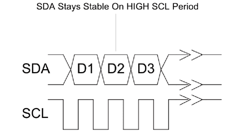
- Data line, SDA is of HIGH logic in idle state, so the transmission between devices must be made at the same logic level so that there is no chance of any type of data transmission error.
- The synchronous clock line acts as the control signal for all operations and is the only way in which all devices connected understand the data frames or packets sent by the master.
- Furthermore, Data is sent into the series form like the other data transmission. But the speed and dual transmission via a single data line need some extra bits for indicating whether the data is sent by the master or the slave.
- Data consists of these bits:
- Start bit
- Address block consists of 7-10 bits (usually 7).
- Read/Write a bit
- Acknowledge/Not-Acknowledge bit (ACK/NACK)
- Main Data byte of size 8 bits(1 Byte = 8 Bits), if multiple bit data frame is sent then an additional data bits along with Acknowledge/Not-acknowledge bits are added.
- Ending Acknowledge/Not-Acknowledge bit
- Stop Bit
- These above-all bits make a data packet or frame which is sent via an SDA line for data transmission.
I2C Start/Stop Bit

- As the idle state of the data pin is HIGH, so without proper start or stop bit parameters, the microcontroller will see this as the normal signal and won’t respond to it.
- To avoid this, the Data signal is pulled from HIGH to low in case of the start bit and from low to HIGH in case of the Stop bit. But to avoid any wrong detection of data these bits must be set in a different way as the others.
- So as to avoid any such confusion, the start and stop bit is pulled from High to low or vice versa before the state of the clock cycle changes, i.e., between the High bit of the Clock cycle.
- These two are the only bits that are set in such a manner so that their rising and falling coincide in between the clock cycle. So as to make the microcontroller or the devices understand and distinguish between the start and stop signal/data bit from the rest of the data bit.
Application of I2C protocol
Normally we are using this protocol to connect the hardware with the microcontroller such as LCD with Arduino.
if you are using Arduino then you can see this I2C Example.
LCD with Arduino using I2C protocol
NodeMCU LCD Tutorial Using I2C Module
I2C Scanner | What is I2C on Arduino?
What is Pulse Sensor and Its Working | Heart Beat
Gimbal Stand Using Arduino And MPU 6050 | Arduino projects
RFID RC522 Module | RFID Sensor | Working | Description
there are many examples more which you can see on our website. Apart from the Arduino, you can see the various controller using I2C to connect the sensor.
Address Block
- This block consists of 7-10 bits, but usually, it is 7. These bits store the address information of the devices for making a transmission to a specific device.
- These bits are necessary as there are 128 different addresses that can be used to address different slaves. So in order to send data to a specific slave in multiple slave configurations or usually in a single slave configuration also I2C address of the device is used for making a transmission.
- The address of the device is not the only thing that is used to make communication, but also the specific register address is used for either writing or reading the data from a specific register.
- The address sent by the master must be the same as that of the slave in order to make further communication. But if the address is different, the SDA line will remain HIGH as that of the idle state.
Read/Write Bit
- This bit is used to tell whether to read or write data from or to the slave from the master. This bit act as an 8th bit for the address and forms a complete byte of data for the address block.
- The LOW bit indicates that the master will write data to the slave to the specific address, and a HIGH bit will read data from the slave from a specific register.
- Also, make sure after this bit all the operations or bits sent or received from either slave or master will be understood as data byte followed by the ACK/NACK bit.
- So, a stop bit is needed to end the communication between the slave and the master. Or the master or slave will continue communicating whether or not the data is actually what you want to send or not.
Acknowledge/Not-Acknowledge Bit
- This bit act as a feedback bit which affirms the confirmation of complete and correct data. This bit is sent by the slave or the specific receiver in multiple slave configurations.
- The Acknowledge bit is sent by the specific slave by pulling the SDA or data line low during a HIGH clock cycle or HIGH SCL cycle, And the Not-Acknowledge bit by pulling the line passively HIGH and not performing any operation.
- The specific slave which master corresponds to Send the Acknowledge while the other slaves (multiple salve configuration) send a Not-Acknowledge bit to the master.
- This byte confirms the receiving of a byte of data and affirms the acceptance of the next transfer which can be data or stop byte or repeated start.
Data Byte IN I2C
- This block consists of 8 bits or a byte of data followed by an ACK/NACK bit which is necessary for every byte of data transfer.
- This byte is synchronized with the clock cycle and is the most important part of the whole communication, as all the required information is encoded in this block.
- There is no limit to the number of the data block that can be sent, but each byte of data must be followed by an ACK/NACK bit for confirmation and continuation of the next bit or byte.
I2C connection
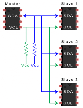
- This communication or protocol has the simplest connection or interfacing as you just have to connect the SCL & SDA of the master to the slave or multiple slaves.
- There can be two ways (3rd used very rarely) in which connection can be made single master single slave & single master multiple slaves. These two are mostly used and are very easy to operate, but you just need to have the I2C address of each slave accurately to communicate with them.
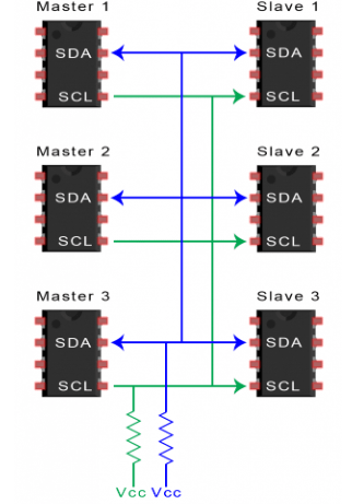
- The third type of connection is not commonly used but is Multiple masters, and multiple slaves. This communication or transmission is done in order to transmit data from multiple slaves to multiple masters as there is a different task each master has to perform.
- Multiple master multiple slave connection creates a hustle between the master and each master needs to wait before the previous master completes the communication.
- In both multiple masters multiple slaves and single master multiple slaves, both SDA & SCL lines need to be pulled up the high reference voltage of the microcontroller on which it is operating.
- The pull-up resistor can vary from 2.2KΩ to 10KΩ, which depends upon the speed of the data transfer you want.
- Also in the case of varying logic levels of the slave and master, it is advised to use a logic level shifter instead of using the DIY resistor method. As this method can result in changing the data and in worst cases not working correctly.