
Hello Friends, welcome back to another informational post on the basic electronics section. Today I’m going to discuss the UART protocol, which is quite popular among beginners and hobbyists.
- Among many communications like SPI, I2C, I2S, and many others, the most highly used either knowingly or unknowingly is UART Communication, which is used by almost all microcontroller and development boards used nowadays.
- UART Stands for Universal Asynchronous Receiver Transmitter, which slightly defines the type of communication it is. This communication is not new but used before the other, but the development has done in this communication which makes it different from previous ones.
- In mostly earlier days of Computer and removable peripherals like Mouse, Keyboard, Printers, Modems, etc. The UART communication was used but in Parallel Connection, as now seen in the RAM and PCI slots, but now removable peripherals are equipped with USB (Universal Serial Bus).
- Also, many UART to USB converters is used for programming different microcontrollers like the most famous Atmega328P and many others.
There are different types of communication protocol
UART Protocol
usually, we use these protocols in most of our projects.
Table of Contents
What is UART Protocol?
- UART – Universal Asynchronous Receiver Transmitter. So here word Asynchronous is used which is used that there is not any type of signal like a clock line as in the case of SPI, I2C, and I2S protocols. These use a clock signal in parallel with a data signal to read and write data from master to slave or vice-versa.
- As mentioned above, in the early days of UART communication parallel data communication was done between peripheral devices, but now it has been replaced with USB or USB to UART communication.
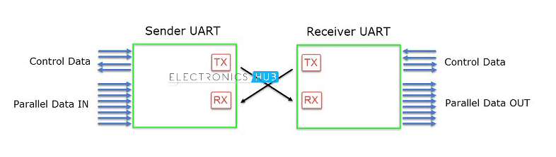
- UART protocol uses 2 wire Rx & Tx which is the same for all devices using this protocol. Here Rx-Receiver & Tx-Transmitter these two wires are hooked to any UART to USB converter or UART to Serial converters for making communication between the Master and the Slave.
- If both devices have Rx & Tx pins then it can be used directly by hooking the Rx pin of one to the Tx pin of the other and vice-versa. But in this case, also you have to make sure that the logic level of both devices are same or the data transmission error or data corruption may happen during transmission.
Parallel Data Communication In UART protocol

- This is the type of UART communication preferred in older days, but as of now replaced with USB or Serial data communication.
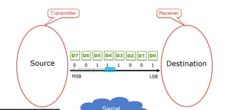
- In this communication, an 8-bit parallel data communication is established between two devices.
- This type of transmission is fast as compared to that of serial communication, as the data is being transmitted in the form of individual bits in parallel lines or in parallel addresses.
- Modern computers use this technology mostly in PCI and Rams as these need fast processing for matching the speed this and upcoming generations needs for computing.
Series Data Communication
- This is the second type of UART communication or UART Interfaced used, and it’s the most common and used in almost all microcontrollers and development boards to program transmit data and much other stuff.
- In this communication, only two wires are used for the whole communication, one is for transmitting the data (Tx) and the other is for receiving the data (Rx).
- This type of transmission is quite slow as compared to parallel data communication as the whole data is set into a series including some more processing data bits used for verifying the correct set of data bits transmission.
UART DATA
- First, this heading covers all the structure or composition of the data packet transmission rules with their definition.
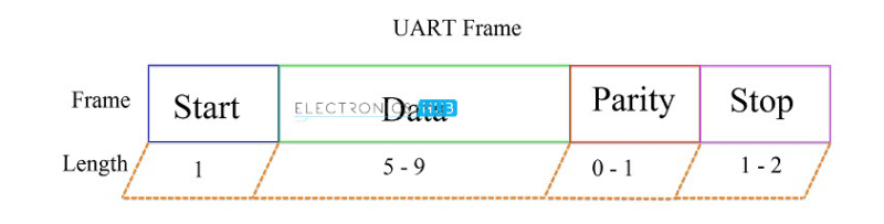
Composition/Structure of the Data Packet/Frame:
START BIT
- The idle state of the data line is high, so whenever there is no transmission of data, the line is kept high to make the receiving device understand that the pin is idle or not transmitting any data.
- A single bit according to the selected baud rate of the transmission is added before the actual data, which is the starting bit. It marks or makes the receiving device understand that the data is being sent after the current bit, so start reading.
- The starting bit is pulled from HIGH to LOW, that is, from 1 to 0
DATA BITS
- The Data bits are the actual data that contains the information which needs to be transmitted. The bits can vary in size from 5-9 bits. Depending upon the size of the data packet.
- The data bits are formed by the D-Flip flops which convert parallel data coming from either CPU or USB converter into a series of bits that form a 5-9 bit long data packet.
PARITY BIT
- This is an optional bit and might, might not be used in every case, which means it acts as a verifying bit for the data packet received as in some cases data transmission error may occur.
- This bit defines two states the data packet is, either even or odd, which determined that the data bits send are of odd parity or even. This ensures data verification in case of data loss.
- The data received is known to be correct and complete when the parity bit and the data bits matches, else data error occurred
STOP BIT
- This is the same as the starting bit, but this bit act as the signal for the microcontroller or devices to make it understand that the data transmission ends here.
- The data is pulled from low voltage signal to high voltage signal for at least two bits, but sometimes only one is also used.
Transmission Rules in UART protocol
- Since this is an Asynchronous data transfer so some measure to make both devices understand the same language needs to be set for this except these 4 parameters, one major and most important parameter is needed.
- START BIT
- DATA BITS
- PARITY BITS
- STOP BITS
- baud rate this is the importance which acts as a clock cycle in cases of a synchronous data transfer. This is directly proportional to the speed with which the data is being transferred.
- But is inversely proportional to the bit duration or size of a bit in a clock cycle. This needs to match between both the transmitting and the receiving devices in order for a successful and correct data transfer.
Different UART Devices
There are many UART Devices that we have used and demonstrated in different articles on our website. Here are a few of them with their default configuration speed and various other information.
UART Arduino | Arduino UART protocol
- One of the most famous Microcontrollers is Arduino UNO also it is very easy to learn and make projects on. All Arduino MIcrocontrollers have UART-Serial Communication, UART Arduino
- All Arduino boards have at least a default serial port D0-Rx, D1-Tx
- Arduino Mega 3 additional serial ports: Serial1 on pins 19 (RX) and 18 (TX), Serial2 on pins 17 (RX) and 16 (TX), and Serial3 on pins 15 (RX) and 14 (TX).
- Arduino Due 3 additional 3.3V TTL serial ports: Serial1 on pins 19 (RX) and 18 (TX); Serial2 on pins 17 (RX) and 16 (TX), Serial3 on pins 15 (RX) and 14 (TX).
- You can use Baudrate ranging from 300 to, 1152000, where 9600 is the default baud rate for UART Arduino communication for all boards.
ESP32 UART | ESP8266 UART Protocol
- All ESP32 | ESP8266 devices have UART Serial port on PIN 40(RXD) & 41(TXD) on QFN 48 SMD Package, i.e., also GPIO # & GPIO 1 Respectively.
- The Supported Baudrate for ESP32 (ESP32 UART & ESP8266) is up to 4Mbps, which is very fast as compared to Arduino Boards.
- ESP32 can have 3 serial ports using the software serial library, including the default one.
- ESP8266 also has the same baud rate as ESP32, but the difference is that the pin count is less and there is no other complete Serial port(excluding the second Tx-only serial port).
Raspberry Pi UART
- Raspberry Pi are another most famous Single Board Computer also microcontroller, it features not only all feature of a low edge computer but also a complete microcontroller task.
- All Raspberry Pi have Default Raspberry Pi UART Serial port on pins GPIO14 (TXD0) & GPIO15 (RXD0). These can be used in all the ways as that in Arduino and ESP, but you need to have proper code in python or any other language you like.
- The Experimented Baudrates for Raspberry Pi is upto 1152000 so far I have used without overclocking them.
OTHER Devices like Bluetooth/GSM/GPS
- Other Devices like HC–05 Bluetooth or GSM and GPS devices also used Serial interface to communicate with the Microcontroller.
- The default baud rates for all devices are different, but you can change them using the AT commands.
Application of UART Protocol
Bluetooth Controlled Servo motor project | Arduino servo motor project
SPY Robot Using Arduino With Bluetooth Controls | Arduino robot
Home automation using Arduino and bluetooth
How to make Arduino Bluetooth rc car
There are many other examples of UART Protocol. if you have any doubts or any problems you can