Table of Contents
RFID Module
RFID Sensor is the most common sensor used for security and authentication purposes. It is rather cheap than other biometrics projects sensors which are used nowadays.
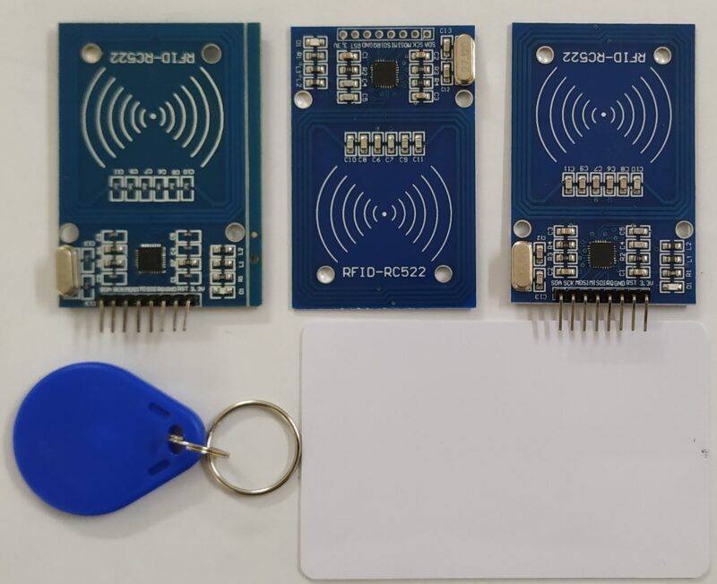
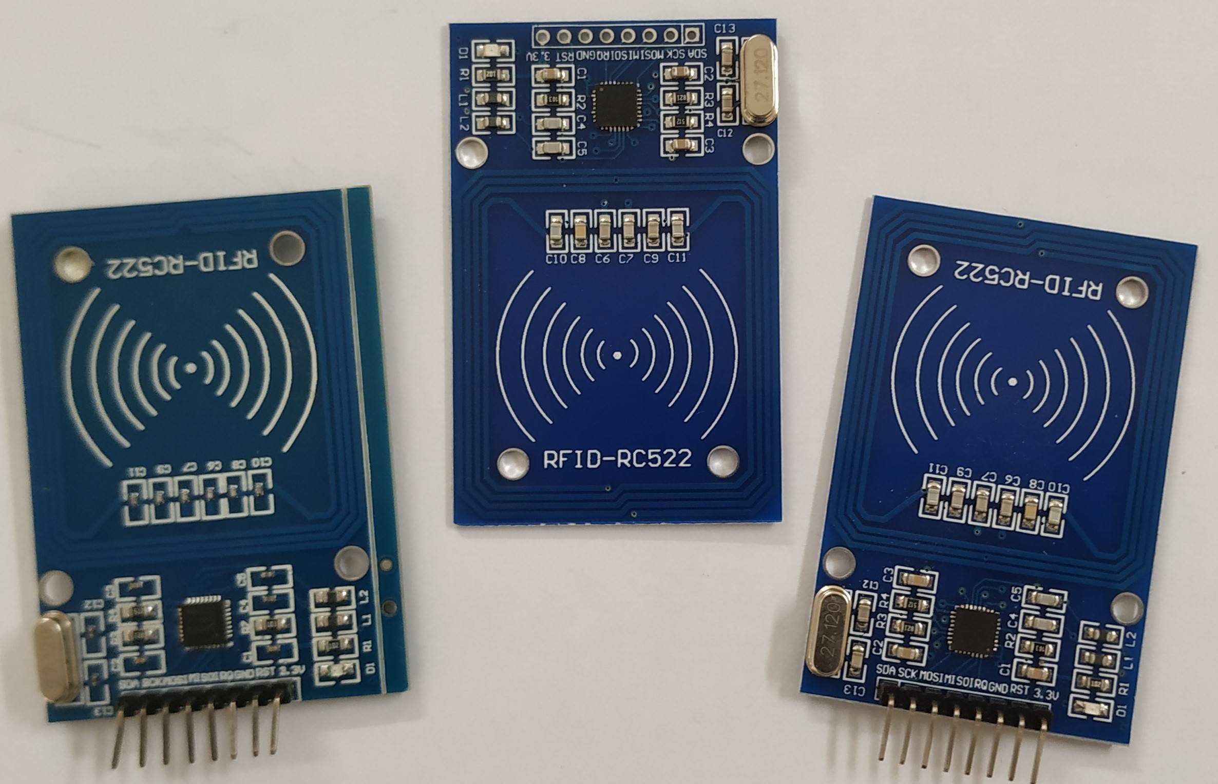
- This sensor is rather very interesting to other sensors which we have explained so far. It packages or in the box contents are RC522 Main Sensor, RF card & a MASTER Card.
- It comes with SPI protocol which enables it to be used with almost any microcontroller from ATTiny to Raspberry Pi and other more advanced boards.
- Along with this, it also has a drawback that it can only read specific types of RFID tags. Not all tags, or we can say tags that are not compatible with 13.56 MHz frequency, cannot be used.
- Also, it works only on 3.3V also logic level is highly required with this level, or you can use a logic-level converter for compatibility.
- Besides, the distance between the card and RFID module plays a major role in data transfer and communication which is needed to be less than 3 cm.

RFID RC522 Construction

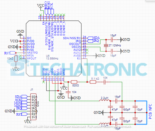
- Above is the given and Expected schematic of the RC522 RFID Sensor. This schematic is not guaranteed to be accurate, the values and components may differ according to the versions.
- The main IC which is used here is MFRC52202HN1,151. The complete IC name is important, as the last 3 numbers 151 represent the model of the IC. Which is different for other versions.
- This IC is tolerant to 3.3V only, so the logic level of the IC and overall sensor is 3.3V. Also, the microcontroller you are using to control, i.e., read and write data to cards using the sensor must be at 3.3V logic level.
- The Blue color wire which is indicated in the schematic is the PCB NFC coil which is used to make communication with the RFID cards. Also, the VCC marked on the schematic is actually 3.3V power line along with GND.
- On the PCB of the sensor, you’ll see there is no Copper area in the region of the NFC Coil. This is done to avoid any error and break of communication during data exchange between RFID cards and sensor.
RFID Working
- There are two module in the RFID module. one is RFID tag and other is RFID reader
- RFID Tag have some coil inside the tag or card which get excited when comes near to the reader and transmit the information to the reader.

RFID Reader
RFID Tags
- rfid Reader have also one coil which generate the mutual induction to the rfid tag coil and transfered the electricity at that time. at that same time the reasder read the tag information.which can be visible to our serial monitor.
- The working of this sensor is not that hardware based as compared to others. More or less, it is controller by the microcontroller using the library provided on the GitHub.
- For more information about the working of the IC i.e., MFRC52202HN1,151 you can visit it’s Datasheet. Overall, this is the powerful IC which is utilizes not only the NFC coil to provide power but also to make communication As other NFC readers.
- The SPI and I2C communication both can be used to control. Also, Hard reset feature is also available using code as stated in the datasheet. Overall IC works on 27.12MHz frequency, but the RFID cards work on 13.56MHz.
- Rest is the play of the code and the microcontroller, as datasheet states that it provided uninterrupted communication. The data rate of the 10 Mbits/s is stated in the datasheet, but the actual condition depends on the microcontroller and baud rate used during communication.
Advantages:
- The first and the most important advantage of the sensor is of the wireless communication and transfer of data for authenticity.
- Secondly, many types of RFID cards can be read and write using this module. Though it is not the best option to use but for small DIY projects it is good.
- It supports SPI protocol, so there is no issue of speed and pins as it can easily be connected to any of the microcontroller.
Disadvantages:
- Most importantly, it supports only of 3.3V logic level, due to which it needs either a logic level converter or a 3.3V microcontroller.
- Sometimes due to slightly increase of the transmission, the data transfer can be obstructed, which is frustrating and sometimes also to reset the microcontroller.
- No onboard status led is provided for indicating reading and writing status of the RFID module. Also, no LDO is provided on board, which means you have to make sure to connect it to 3.3V power supply only.
RFID Module Price & Availability:
- This module is very common and is easily available in the online and offline market. (People residing in INDIA Only), Due to certain issues the prices of the sensor are raised. So, the price cannot be confirmed for both online and offline purchase. But few websites which you can refer to buy module:
- All components are together-BUY LINK

FAQ
Q. What is the Logic level of the RC522 RFID Module?
As mentioned above in the article, the Logic level of the RC522 RFID Module is 3.3V. The power supply range is also the 3.3V strictly. Any voltage higher or lower can result in severe damage to the module.
Q. What is the RFID Card frequency of the RC522 RFID Module?
RFID cards frequency is 13.56 MHz. It is the frequency of the cards which you should keep in mind while purchasing spare RFID cards. But the module works on 27.12 MHz.
Q. What is the maximum distance under which data transfer is possible between RC522 RFID Module and RFID Cards?
Actually, I have not measured it accurately, but it is about 4-5 cm upto which data transfer is possible. Over this, data transfer is impossible.
Q. Can Arduino UNO and similar board be used without any logic level converter for RC522 RFID Module?
Yes it should work as for me, it worked. But if it doesn’t work, you can buy a cheap logic level converter of 4 terminal and use it to communication between any microcontroller and RFID Module.
Latest RFID Project
RFID Sliding Door Lock Using Arduino|rfid project
Windows Login Using RFID Module And Arduino | RFID Project
RFID Based Attendance System Using Arduino


