

The pulse sensor is a vital sensor in the field of heath-related devices, and it comes in various types and options.
- This is the most basic sensor to start with if you want to measure or play with heart beat sensor or pulse sensor. It is very cheaply available in the offline and online markets.
- This sensor is very compact and small relative to other modules available in the market. But its working and efficiency are not affected by its size for the small purpose. For more, visit its articles.
- If you want to work with a more effective sensor, then you should not use this for professional work. Moreover, you can shift to MAX30102/MAX30105.
- It is a simple circuit to detect the reflection of light that occurs due to the reflection from the blood flowing in the blood vessels.
- The output of the sensor is delivered through the single pin, which is the out pin. It sends signals to the microcontroller in the form of pulse signals.
- This heart beat sensor is fully Arduino compatible.

Table of Contents
Construction of Pulse sensor | Heart Rate Sensor
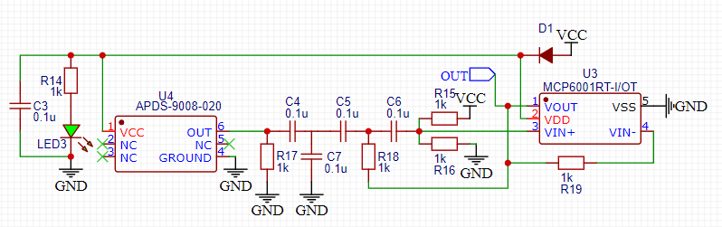
- Above is the schematic designed by myself from the schematics found on the internet. All the names of the components used are stated in the circuit, or you can download them from the link provided.
- The circuit consists of two main ICs that are namely APDS-9008 & MCP60001RT. These two are the heart of the sensor and the others are passive components.
- APDS-9008 is a Miniature Surface-Mount Ambient Light Photo Sensor in this Heart beat sensor that is used to sense the reflected light coming from the blood flow from blood vessels underneath the skin. It is used for small and simple projects, but for professional use the one I have recommended above.
- MCP60001RT is an Op-Amp that is used to amplify the signal coming from APDS-9008, which converts the received light from reflection into the voltage pulse signals.
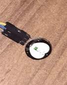
- The Green LED is used for reflection purposes and is received by the APDS-9008 photosensor.
Working Heart beat sensor | Pulse Sensor
- The sensor works in a very simple manner of reflection of light. The principle which is used is called Photoplethysmogram. Rest is the play of algorithms used in data processing coming from the sensor.
- The light which is used for reflection is generally RED or GREEN based on the principle of the Photoplethysmogram. In all the other heart beat sensor these two light is used also the one I have recommended above.
- The received light is converted into a voltage signal pulse which is sent directly to low logic level microcontrollers directly or by the use of an Op-Amp in between.
- The Op-amp used in this circuit is MCP6001RT, which is best for the useable logic level for every microcontroller. For more information, visit the datasheet provided above of the Op-Amp.
Advantages
- Firstly, it is simple to use and provides single-pin Data output which is kind of easier to handle as compared to other sensors like MAX3010x series sensors which use the I2C protocol.
- Moreover, for small DIY projects, this sensor is quite accurate and data extracting and processing is also simple. Also, it can be used with almost any microcontroller.
- Greenlight used for sensing the pulses is more useful than the red light as per the principle of the Photoplethysmogram while the other sensor like max & MAX30102, MAX30100 uses red light
Disadvantages
- The main disadvantage of this sensor is that the distance between the skin and the sensor affects a lot, also the shade of the skin varying from while to dark reduces the light entering into the blood vessels.
- The pulse rate sensor sometimes shows inappropriate reading and can sometimes change the average of the data also may arise a problem.
- As all the electronic parts are very open to the skin, they might be dangerous if not used carefully. Also, the pins for powering and delivering the data are at the end parallel to PCB not perpendicular.
- HDI and flex boards. Even though the PCBs they produce differ a lot regarding functionality and areas of use. I am impressed with the quality of the boards, the delivery time, and the cost-effectiveness
Applications
- There are various interesting projects that can be built out of this sensor. Also, interfacing of heart beat sensor is very easy with most of the microcontrollers some of the projects and tutorials are mentioned below.
- Pulse oximeter NodeMCU.
- Pulse sensor with Arduino.
- Pulse Sensor Interfacing With Arduino | How Pulse Sensor works with Arduino.
- many other supported microcontrollers will be updated soon.
FAQ
Q. What is the working voltage and the logic level of the Pulse Sensor?
The working voltage of the Pulse Sensor is from 3.0V- to 5.0V and for logic level is 0.3V-5V. The logic level depends upon the input voltage to the Pulse sensor.
Q. Can we give power to Arduino using an ac source while measuring with Heart beat sensor?
No, it is not recommended and advised to avoid power in the microcontroller using any AC source including your laptop if connected to charging. Because the AC source can make the person on which the experiment is performed mild shock from the sensor as all the electronics parts are open.
Q. Which sensor is better for measuring accurate heart rate Pulse sensor or MAX3010x Series?
It solely depends on the user preference, the features the user need task it needs to be performed, and other thing that needs to keep in mind before choosing a sensor. But in my opinion, if you can then go for the MAX3010X series as those are far better than these.