
Hello there, Are you making a project that uses the pulse sensor but you’re not sure how? Do you want to know how the pulse sensor works? If so, you have come to the right destination. In this article, we’ll go over how to function, use, and interface the pulse sensor with Arduino in a step-by-step guide. We will also provide the circuit diagram and Arduino code in this article. Hence, I hope you find this useful. We at Techatronic have already uploaded several Arduino Tutorials and detailed project guides related to Arduino which will be useful to learn the basics and programming of Arduino.
What Is a pulse Sensor?
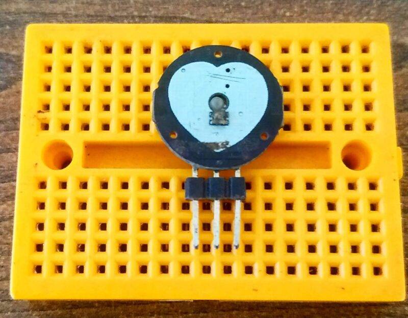
The pulse sensor is also known as a Heart-Rate sensor or Heartbeat sensor. As the name suggests, it is used to read the heartbeat pulses using any microcontroller, for example, Arduino UNO.
This is also used in many DIY projects by enthusiasts to add the heartbeat pulses-based working including SmartWatches. These types of sensors are used in many commercial areas, especially in the Health care and Health monitoring sector. The ones used in this are more accurate and costly.
This Sensor is very easy to use even for beginners, as it does not require any complex circuit making. It is a plug-and-play type sensor. you can also make your own Heartbeat counter at home using this sensor and display it on an OLED screen.

How Does a Pulse Sensor Work?
The sensor works on the principle of reflection of light. There are two parts to this sensor. one is the light-emitting-diode and the other is an ambient light sensor. Firstly, the light emitted falls on the blood cells in the veins and reflects back some light.
The ambient sensor detects the light and sends the data signal to the host after some amplification. The signal is the analog type which ranges between the values 0 and 1023.
The sensor needs only one wire to share and communicate data with the host. This draws around 3mA at both 3.3V and 5V.
Components Required for Pulse Sensor works with Arduino
| Arduino UNO | BUY LINK |
| Pulse Sensor | BUY LINK |
| Jumper Wires | BUY LINK |
| Breadboard | BUY LINK |
| LED | BUY LINK |
| 220-ohm Resistor | BUY LINK |
| USB cable to connect Arduino UNO | BUY LINK |
You can buy all components together-BUY LINK

Pulse Sensor Interfacing With Arduino Circuit Diagram

|
Arduino UNO |
Pulse Sensor | |
|
( +5V ) |
( + ) Positive | |
|
GND |
( – ) Positive | |
|
A0 Pin |
( S ) Signal | |
|
Arduino UNO |
LED |
220-ohm Resistor |
|
D11 Pin |
Anode Terminal |
|
|
GND |
|
Terminal 1 |
|
|
Cathode Terminal |
Terminal 2 |
- VCC of the sensor to 5V pin of Arduino UNO.
- GND of sensor to GND of Arduino UNO
- Signal out of sensor to A0 of Arduino UNO
- Negative’-‘ of LED to GND of Arduino UNO with 220-ohm Resistor in between
- Positive’+’ of LED to D11 of Arduino UNO
Pulse Sensor Interfacing With Arduino Code
 int pulsePin = A0;         // Pulse Sensor purple wire connected to analog pin A0
 int blinkPin = 11;        // pin to blink led at each beat
 // Volatile Variables, used in the interrupt service routine!
 volatile int BPM;          // int that holds raw Analog in 0. updated every 2mS
 volatile int Signal;        // holds the incoming raw data
 volatile int IBI = 600;       // int that holds the time interval between beats! Must be seeded!
 volatile boolean Pulse = false;   // "True" when User's live heartbeat is detected. "False" when not a "live beat".
 volatile boolean QS = false;    // becomes true when Arduoino finds a beat.
 static boolean serialVisual = true;  // Set to 'false' by Default. Re-set to 'true' to see Arduino Serial Monitor ASCII Visual Pulse
 volatile int rate[10];           // array to hold last ten IBI values
 volatile unsigned long sampleCounter = 0;     // used to determine pulse timing
 volatile unsigned long lastBeatTime = 0;      // used to find IBI
 volatile int P = 512;           // used to find peak in pulse wave, seeded
 volatile int T = 512;           // used to find trough in pulse wave, seeded
 volatile int thresh = 525;        // used to find instant moment of heart beat, seeded
 volatile int amp = 100;          // used to hold amplitude of pulse waveform, seeded
 volatile boolean firstBeat = true;    // used to seed rate array so we startup with reasonable BPM
 volatile boolean secondBeat = false;   // used to seed rate array so we startup with reasonable BPM
 void setup()
 {
  pinMode(blinkPin,OUTPUT);     // pin that will blink to your heartbeat!
  Serial.begin(115200);       // we agree to talk fast!
  interruptSetup();         // sets up to read Pulse Sensor signal every 2mS
                   // IF YOU ARE POWERING The Pulse Sensor AT VOLTAGE LESS THAN THE BOARD VOLTAGE,
                   // UN-COMMENT THE NEXT LINE AND APPLY THAT VOLTAGE TO THE A-REF PIN
                   //  analogReference(EXTERNAL);
 }
 // Where the Magic Happens
 void loop()
 {
   serialOutput();
  if (QS == true) // A Heartbeat Was Found
   {
    // BPM and IBI have been Determined
    // Quantified Self "QS" true when arduino finds a heartbeat
    serialOutputWhenBeatHappens(); // A Beat Happened, Output that to serial.
    QS = false; // reset the Quantified Self flag for next time
   }
  delay(20); // take a break
 }
 void interruptSetup()
 {
  // Initializes Timer2 to throw an interrupt every 2mS.
  TCCR2A = 0x02;   // DISABLE PWM ON DIGITAL PINS 3 AND 11, AND GO INTO CTC MODE
  TCCR2B = 0x06;   // DON'T FORCE COMPARE, 256 PRESCALER
  OCR2A = 0X7C;   // SET THE TOP OF THE COUNT TO 124 FOR 500Hz SAMPLE RATE
  TIMSK2 = 0x02;   // ENABLE INTERRUPT ON MATCH BETWEEN TIMER2 AND OCR2A
  sei();       // MAKE SURE GLOBAL INTERRUPTS ARE ENABLED
 }
 void serialOutput()
 {  // Decide How To Output Serial.
  if (serialVisual == true)
  {
    arduinoSerialMonitorVisual('-', Signal);  // goes to function that makes Serial Monitor Visualizer
  }
  else
  {
    sendDataToSerial('S', Signal);   // goes to sendDataToSerial function
   }
 }
 void serialOutputWhenBeatHappens()
 {
  if (serialVisual == true) // Code to Make the Serial Monitor Visualizer Work
   {
    Serial.print(" Heart-Beat Found "); //ASCII Art Madness
    Serial.print("BPM: ");
    Serial.println(BPM);
   }
  else
   {
    sendDataToSerial('B',BPM);  // send heart rate with a 'B' prefix
    sendDataToSerial('Q',IBI);  // send time between beats with a 'Q' prefix
   }
 }
 void arduinoSerialMonitorVisual(char symbol, int data )
 {
  const int sensorMin = 0;   // sensor minimum, discovered through experiment
  const int sensorMax = 1024;  // sensor maximum, discovered through experiment
  int sensorReading = data; // map the sensor range to a range of 12 options:
  int range = map(sensorReading, sensorMin, sensorMax, 0, 11);
  // do something different depending on the
  // range value:
 }
 void sendDataToSerial(char symbol, int data )
 {
   Serial.print(symbol);
   Serial.println(data);
 }
 ISR(TIMER2_COMPA_vect) //triggered when Timer2 counts to 124
 {
  cli();                   // disable interrupts while we do this
  Signal = analogRead(pulsePin);       // read the Pulse Sensor
  sampleCounter += 2;             // keep track of the time in mS with this variable
  int N = sampleCounter - lastBeatTime;    // monitor the time since the last beat to avoid noise
                        // find the peak and trough of the pulse wave
  if(Signal < thresh && N > (IBI/5)*3) // avoid dichrotic noise by waiting 3/5 of last IBI
   {
    if (Signal < T) // T is the trough
    {
     T = Signal; // keep track of lowest point in pulse wave
    }
   }
  if(Signal > thresh && Signal > P)
   {     // thresh condition helps avoid noise
    P = Signal;               // P is the peak
   }                    // keep track of highest point in pulse wave
  // NOW IT'S TIME TO LOOK FOR THE HEART BEAT
  // signal surges up in value every time there is a pulse
  if (N > 250)
  {                  // avoid high frequency noise
   if ( (Signal > thresh) && (Pulse == false) && (N > (IBI/5)*3) )
    {
     Pulse = true;                // set the Pulse flag when we think there is a pulse
     digitalWrite(blinkPin,HIGH);        // turn on pin 13 LED
     IBI = sampleCounter - lastBeatTime;     // measure time between beats in mS
     lastBeatTime = sampleCounter;        // keep track of time for next pulse
     if(secondBeat)
     {            // if this is the second beat, if secondBeat == TRUE
      secondBeat = false;         // clear secondBeat flag
      for(int i=0; i<=9; i++) // seed the running total to get a realisitic BPM at startup
      {
       rate[i] = IBI;
      }
     }
     if(firstBeat) // if it's the first time we found a beat, if firstBeat == TRUE
     {
      firstBeat = false;          // clear firstBeat flag
      secondBeat = true;          // set the second beat flag
      sei();                // enable interrupts again
      return;               // IBI value is unreliable so discard it
     }
    // keep a running total of the last 10 IBI values
    word runningTotal = 0;         // clear the runningTotal variable
    for(int i=0; i<=8; i++)
     {        // shift data in the rate array
      rate[i] = rate[i+1];         // and drop the oldest IBI value
      runningTotal += rate[i];       // add up the 9 oldest IBI values
     }
    rate[9] = IBI;             // add the latest IBI to the rate array
    runningTotal += rate[9];        // add the latest IBI to runningTotal
    runningTotal /= 10;           // average the last 10 IBI values
    BPM = 60000/runningTotal;        // how many beats can fit into a minute? that's BPM!
    QS = true;               // set Quantified Self flag
    // QS FLAG IS NOT CLEARED INSIDE THIS ISR
   }
  }
  if (Signal < thresh && Pulse == true)
   {  // when the values are going down, the beat is over
    digitalWrite(blinkPin,LOW);      // turn off pin 13 LED
    Pulse = false;             // reset the Pulse flag so we can do it again
    amp = P - T;              // get amplitude of the pulse wave
    thresh = amp/2 + T;          // set thresh at 50% of the amplitude
    P = thresh;              // reset these for next time
    T = thresh;
   }
  if (N > 2500)
   {              // if 2.5 seconds go by without a beat
    thresh = 512;             // set thresh default
    P = 512;                // set P default
    T = 512;                // set T default
    lastBeatTime = sampleCounter;     // bring the lastBeatTime up to date
    firstBeat = true;           // set these to avoid noise
    secondBeat = false;          // when we get the heartbeat back
   }
  sei();                  // enable interrupts when youre done!
 }// end isr

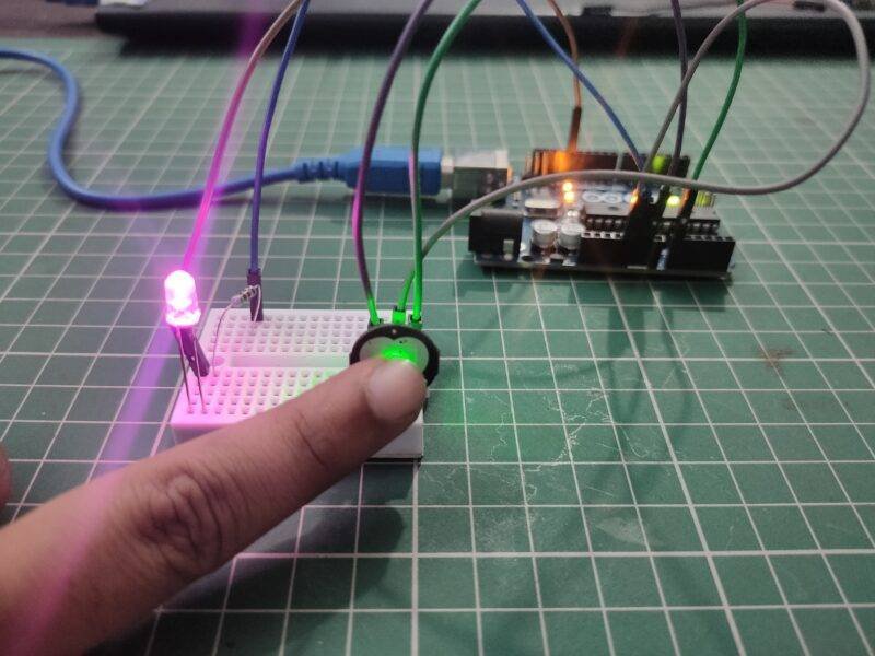
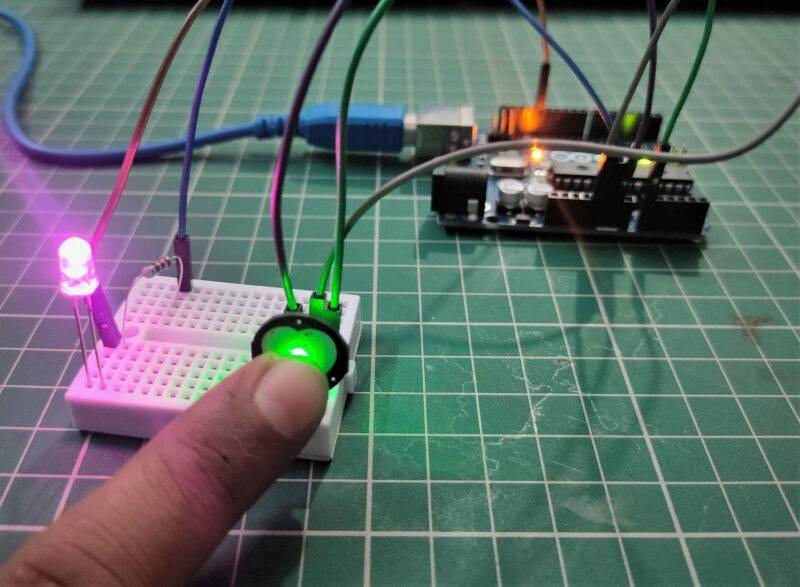
After Uploading the code, the output LED connected to pin 11 of Arduino UNO will mimic the Heartbeat by blinking. I hope you liked this article. If you need any help, you can ask them in the comment section below.