
how to make LED patterns with Arduino
Hey guys, welcome back to the Techatronics, so this is the fourth tutorial of the Arduino course. in this course, we will explain how to make LED patterns with Arduino. as you all see the light which we used to decorate our home during marriage and on any festival there are many lights in a row and all these lights glow in a pattern. in our last tutorial, we made Arduino led blinking guide now this is the next step to learn the Arduino and programming. so if you want to learn the Arduino please follow our tutorial you will learn this course definitely.
you can make numerous examples everything relies on your idea. you can utilize 1-20 LED with N number of the examples. you will learn in this article how to make LED Patterns with Arduino. you will adapt additionally how to utilize the logic, delay, and loop. Arduino is an open-source microcontroller that having 14 GPIO Pins, 6 Analog pins. modified by IDE Arduino Software.
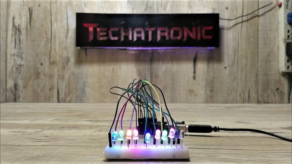
Driven Pattern, flickering with Arduino is an alluring lighting venture. in which we utilize numerous parts which we appeared in underneath. we cause 3 examples with 10 LEDs as you to can find in the photos. first all the LED squint sequentially then speed of flickering change and afterward from the center LED of the upper side and lower side off at the same time so in this post, we are trying to make the various patter and will teach you how to make the led patten using Arduino.
How does it work?
let me clear the working of the system. there are several LED connected with the Arduino and you can connect a lot of LEDs. first glow the first led then first led off and 2nd led will glow likewise 3rd and the rest of all. So, you need to understand the working. there is only two logic we use in the pattern. high and low in digital. we will not use any analog or PWM signal in this project.
Now we will talk about the code. on which pins we will use the LEDs.
Step #1
#define LED_1 1
#define LED _2 2
#define LED_3 3
#define LED_4 4
#define LED_5 5
#define LED_6 6
#define LED_7 7
#define LED_8 8
#define LED_9 9
#define LED_10 10
in the above line, we are assigning and variable LED_1 to the 1 pins of Arduino , variable LED_2 to the 2 pins of Arduino. and the same for the rest of all. as you can see above.
Step #2
The second step is to make a void function as given below:-
Void Setup( )
void setup is the function to set the initial for the main functions. for example to set and output and input pins, setting up of baud rate, initiate another peripheral like Bluetooth, wifi, and much more.
and there are two curly braces {} open and close we have to write the statement of function inside in these braces. there we initiate the program data as given as below
Step #3
{
pinMode{LED_1, OUTPUT};
pinMode{LED_2, OUTPUT};
pinMode{LED_3, OUTPUT};
pinMode{LED_4, OUTPUT};
pinMode{LED_5, OUTPUT};
pinMode{LED_6, OUTPUT};
pinMode{LED_7, OUTPUT};
pinMode{LED_8, OUTPUT};
pinMode{LED_9, OUTPUT};
pinMode{LED_10, OUTPUT};
( according to this statement the LED_1 variable which is assigned above on pin 1 will work as an output. the whole line meaning is pin number 1 will act as an output pin. here is a word pinMode which carr two words pin & Mode. it means on which pin what will be the mode. either OUTPUT or INPUT. as you read above the same instruction applicable for the rest of all. understand in more detail ou must read this Arduino introduction article. where all I have given about it. )
or you can use the ” for loop” instead of writing these all 10 instructions.
example:- for (i=0; i<10; i++)
{pinMode{i, OUTPUT}; }
}
Now in the above step, you define the pin and assign the value in led pattern with Arduino.
in the next step, you will give the command to the LED to glow and off likewise you did before.
Step #4
void loop()
the void loop is the function to write main functions that will run continuously as we know the loop means the program will be run till the break statement inside the loop . for example if I write there a code for led pattern the code will run continuously infinite time.
and there are two curly braces {} open and close we have to write the statement of function inside in these braces.
Step #5
{
digitalWrite(LED_1, HIGH);
digitalWrite(LED_2, HIGH);
digitalWrite(LED_3, HIGH);
(the above statement saying that the LED_1 which is assigned on a pin 1 will be given the HIGH(+5v) value so that LED will glow, digitalWrite is a term which used to write this statement. )
delay(1000);
(according to this statement there will be a delay of 1 sec )
digitalWrite(LED_1, LOW);
digitalWrite(LED_2, LOW);
digitalWrite(LED_3, LOW);
(the above statement saying that the LED_1 which is assigned on pin 9 will be given the LOW(+5v) value so that LED will off, digitalWrite is a term which used to write this statement. )
the above-given program is only for the three led if you want to write the 10 led you need to writ it till the LED_10.
delay(1000);
(according to this statement there will be a delay of 1 sec )
}
there you can use the for loop also as you did before.
Arduino LED pattern program code:-
void setup() {
for(int i=1; i<=10; i++)
{
pinMode(i, OUTPUT);
}
}
void loop() {
for (int m=1; m<=10; m++)
{
digitalWrite(m, HIGH); // turn the LED on (HIGH is the voltage level)
delay(50); // wait for a second
}
delay(200);
for (int m=10; m>=1; m–)
{
digitalWrite(m, LOW); // turn the LED on (HIGH is the voltage level)
delay(50); // wait for a second
}
digitalWrite(10, HIGH); // turn the LED on (HIGH is the voltage level)
delay(50); // wait for a second
digitalWrite(1, HIGH); // turn the LED off by making the voltage LOW
delay(50);
digitalWrite(9, HIGH); // turn the LED on (HIGH is the voltage level)
delay(50); // wait for a second
digitalWrite(2, HIGH); // turn the LED off by making the voltage LOW
delay(50);
digitalWrite(8, HIGH); // turn the LED on (HIGH is the voltage level)
delay(50); // wait for a second
digitalWrite(3, HIGH); // turn the LED off by making the voltage LOW
delay(50);
digitalWrite(7, HIGH); // turn the LED on (HIGH is the voltage level)
delay(50); // wait for a second
digitalWrite(4, HIGH); // turn the LED off by making the voltage LOW
delay(50);
digitalWrite(6, HIGH); // turn the LED on (HIGH is the voltage level)
delay(50); // wait for a second
digitalWrite(5, HIGH); // turn the LED off by making the voltage LOW
delay(100);
digitalWrite(10, LOW); // turn the LED on (HIGH is the voltage level)
delay(50); // wait for a second
digitalWrite(1, LOW); // turn the LED off by making the voltage LOW
delay(50);
digitalWrite(9, LOW); // turn the LED on (HIGH is the voltage level)
delay(50); // wait for a second
digitalWrite(2, LOW); // turn the LED off by making the voltage LOW
delay(50);
digitalWrite(8, LOW); // turn the LED on (HIGH is the voltage level)
delay(50); // wait for a second
digitalWrite(3, LOW); // turn the LED off by making the voltage LOW
delay(50);
digitalWrite(7, LOW); // turn the LED on (HIGH is the voltage level)
delay(50); // wait for a second
digitalWrite(4, LOW); // turn the LED off by making the voltage LOW
delay(50);
digitalWrite(6, LOW); // turn the LED on (HIGH is the voltage level)
delay(50); // wait for a second
digitalWrite(5, LOW); // turn the LED off by making the voltage LOW
delay(200);
digitalWrite(1, HIGH); // turn the LED off by making the voltage LOW
delay(110);
digitalWrite(1, LOW); // turn the LED off by making the voltage LOW
delay(110);
digitalWrite(1, HIGH); // turn the LED off by making the voltage LOW
delay(110);
digitalWrite(1, LOW); // turn the LED off by making the voltage LOW
delay(110);
digitalWrite(1, HIGH); // turn the LED off by making the voltage LOW
delay(110);
digitalWrite(1, LOW); // turn the LED off by making the voltage LOW
delay(110);
digitalWrite(2, HIGH); // turn the LED off by making the voltage LOW
delay(110);
digitalWrite(2, LOW); // turn the LED off by making the voltage LOW
delay(110);
digitalWrite(2, HIGH); // turn the LED off by making the voltage LOW
delay(110);
digitalWrite(2, LOW); // turn the LED off by making the voltage LOW
delay(110);
digitalWrite(2, HIGH); // turn the LED off by making the voltage LOW
delay(110);
digitalWrite(2, LOW); // turn the LED off by making the voltage LOW
delay(110);
digitalWrite(3, HIGH); // turn the LED off by making the voltage LOW
delay(110);
digitalWrite(3, LOW); // turn the LED off by making the voltage LOW
delay(110);
digitalWrite(3, HIGH); // turn the LED off by making the voltage LOW
delay(110);
digitalWrite(3, LOW); // turn the LED off by making the voltage LOW
delay(110);
digitalWrite(3, HIGH); // turn the LED off by making the voltage LOW
delay(110);
digitalWrite(3, LOW); // turn the LED off by making the voltage LOW
delay(110);
digitalWrite(4, HIGH); // turn the LED off by making the voltage LOW
delay(110);
digitalWrite(4, LOW); // turn the LED off by making the voltage LOW
delay(110);
digitalWrite(4, HIGH); // turn the LED off by making the voltage LOW
delay(110);
digitalWrite(4, LOW); // turn the LED off by making the voltage LOW
delay(110);
digitalWrite(4, HIGH); // turn the LED off by making the voltage LOW
delay(110);
digitalWrite(4, LOW); // turn the LED off by making the voltage LOW
delay(110);
digitalWrite(5, HIGH); // turn the LED off by making the voltage LOW
delay(110);
digitalWrite(5, LOW); // turn the LED off by making the voltage LOW
delay(110);
digitalWrite(5, HIGH); // turn the LED off by making the voltage LOW
delay(110);
digitalWrite(5, LOW); // turn the LED off by making the voltage LOW
delay(110);
digitalWrite(5, HIGH); // turn the LED off by making the voltage LOW
delay(110);
digitalWrite(5, LOW); // turn the LED off by making the voltage LOW
delay(110);
digitalWrite(6, HIGH); // turn the LED off by making the voltage LOW
delay(110);
digitalWrite(6, LOW); // turn the LED off by making the voltage LOW
delay(110);
digitalWrite(6, HIGH); // turn the LED off by making the voltage LOW
delay(110);
digitalWrite(6, LOW); // turn the LED off by making the voltage LOW
delay(110);
digitalWrite(6, HIGH); // turn the LED off by making the voltage LOW
delay(110);
digitalWrite(6, LOW); // turn the LED off by making the voltage LOW
delay(110);
digitalWrite(7, HIGH); // turn the LED off by making the voltage LOW
delay(110);
digitalWrite(7, LOW); // turn the LED off by making the voltage LOW
delay(110);
digitalWrite(7, HIGH); // turn the LED off by making the voltage LOW
delay(110);
digitalWrite(7, LOW); // turn the LED off by making the voltage LOW
delay(110);
digitalWrite(7, HIGH); // turn the LED off by making the voltage LOW
delay(110);
digitalWrite(7, LOW); // turn the LED off by making the voltage LOW
delay(110);
digitalWrite(8, HIGH); // turn the LED off by making the voltage LOW
delay(110);
digitalWrite(8, LOW); // turn the LED off by making the voltage LOW
delay(110);
digitalWrite(8, HIGH); // turn the LED off by making the voltage LOW
delay(110);
digitalWrite(8, LOW); // turn the LED off by making the voltage LOW
delay(110);
digitalWrite(8, HIGH); // turn the LED off by making the voltage LOW
delay(110);
digitalWrite(8, LOW); // turn the LED off by making the voltage LOW
delay(110);
digitalWrite(9, HIGH); // turn the LED off by making the voltage LOW
delay(110);
digitalWrite(9, LOW); // turn the LED off by making the voltage LOW
delay(110);
digitalWrite(9, HIGH); // turn the LED off by making the voltage LOW
delay(110);
digitalWrite(9, LOW); // turn the LED off by making the voltage LOW
delay(110);
digitalWrite(9, HIGH); // turn the LED off by making the voltage LOW
delay(110);
digitalWrite(9, LOW); // turn the LED off by making the voltage LOW
delay(110);
digitalWrite(10, HIGH); // turn the LED off by making the voltage LOW
delay(110);
digitalWrite(10, LOW); // turn the LED off by making the voltage LOW
delay(110);
digitalWrite(10, HIGH); // turn the LED off by making the voltage LOW
delay(110);
digitalWrite(10, LOW); // turn the LED off by making the voltage LOW
delay(110);
digitalWrite(10, HIGH); // turn the LED off by making the voltage LOW
delay(110);
digitalWrite(10, LOW); // turn the LED off by making the voltage LOW
delay(110);
}
THE LED pattern with Arduino circuit diagram is given in the video attached below.