

Table of Contents
Introduction
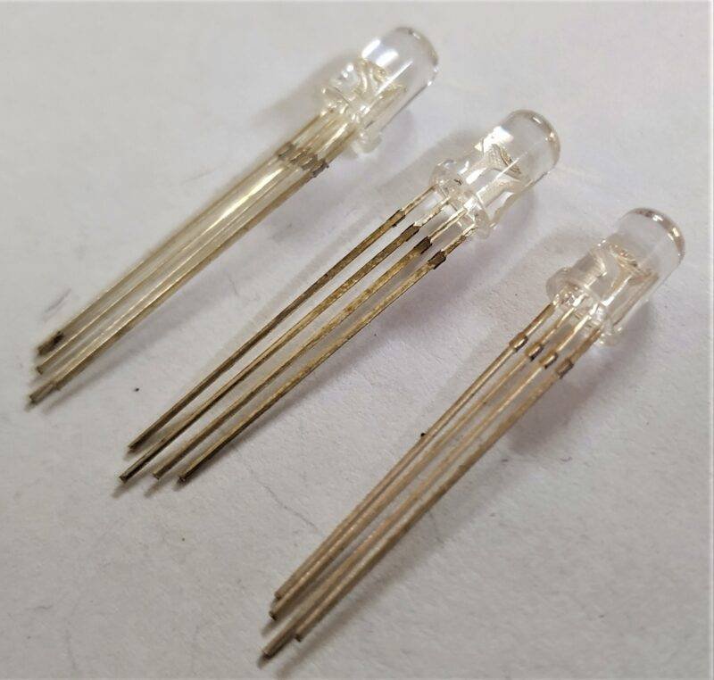
Hey guys, we are back with another new article in the series of ESP8266 tutorials. We hope that you are doing fine. Are you familiar with an RGB LED module? Basically,we can call it a combination of red, green, and blue LEDs, all are bound together in a single LED.
It has four legs, three positive legs for each individual color, and a common ground leg.
So in this post, we are going to learn how an RGB LED module works with a nodemcu board. We have also shared some screenshots, circuit diagrams, and code for your convenience.
You can also read more articles on IoT and Arduino published by us. So are you excited about making it?
Description
In this project,
- either you can use a LED module or you can use an RGB LED only.
- All three colors one by one after a delay of a few seconds.
- You can also modify the sequence and time delay by changing the code.
- LED stands for light-emitting diode which can emit light only when you connect the positive leg with the positive terminal of the battery and the negative leg with the negative terminal.
- While using a LED always use a resistor so that it can prevent the burning of the LED due to high voltage.
- Nodemcu board is a type of microcontroller board with a built-in WiFi module. If you want to use the same RGB LED module with Arduino UNO then check out our article on it.
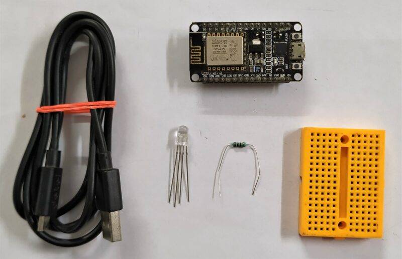
Components Required
| ESP8266 nodemcu | BUY LINK |
| RGB LED | BUY LINK |
| 220-ohm resistor | BUY LINK |
| breadboard | BUY LINK |
| Jumper wires | BUY LINK |
| USB cable for uploading the code | BUY LINK |
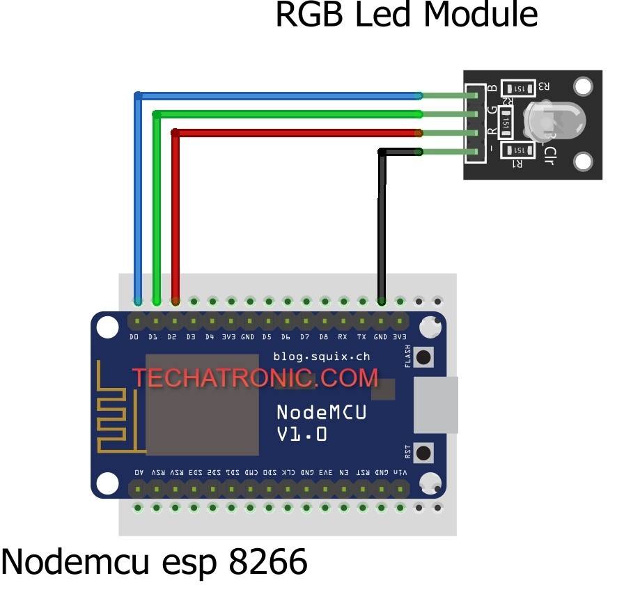
Circuit Diagram for the Project
Connection Table
| Nodemcu esp8266 | RGB LED Module | 220 Ohm Resistor | ||
| GND | Terminal 1 | |||
| ( – ) ( Negative Pin ) | Terminal 2 | |||
| R | G | B | ||
| D2 Pin | Connect | |||
| D1 Pin | Connect | |||
| D0 Pin | Connect |
If you are working with the RGB LED module in ESP8266 tutorial then
- connect the GND pin of the module with the GND pin of the nodemcu.
- Join the R pin (red light) of the module with the digital-2 pin of the nodemcu.
- Connect the G pin (green light) of the module with the digital-1 pin of the nodemcu.
- At last, connect the B pin (blue color) of the module with the digital-0 pin of the nodemcu.
RGB with Common anode
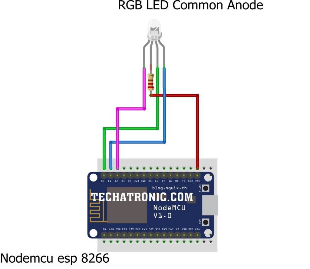
common anode connection
| Nodemcu esp8266 | RGB LED Common Anode | 220 Ohm Resistor |
| D2 Pin | Terminal 1 | |
| D1 Pin | Terminal 2 | |
| D0 Pin | Terminal 3 | |
| Terminal 4 | Terminal 1 | |
| 3V3 | Terminal 2 |
 Common Cathode Circuit diagram
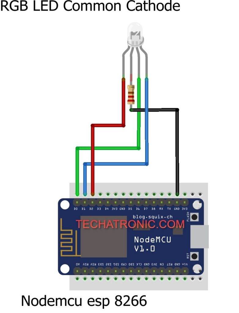 Common Cathode Circuit diagram
Connection Table for common Cathode
| Nodemcu esp8266 | RGB LED Common Cathode | 220 Ohm Resistor |
| D2 Pin | Terminal 1 | |
| D1 Pin | Terminal 2 | |
| D0 Pin | Terminal 3 | |
| Terminal 4 | Terminal 1 | |
| GND | Terminal 2 |
Code for the Project.
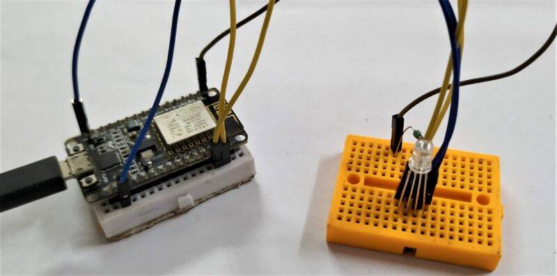
If you are working with an RGB LED then connect the negative leg with the GND pin of the nodemcu via a 220-ohm resistor.
Attach the rest of the pins (for green, blue, and red colors) with the digital pins of the nodemcu as shown above in the circuit diagram for esp8266 tutorial.
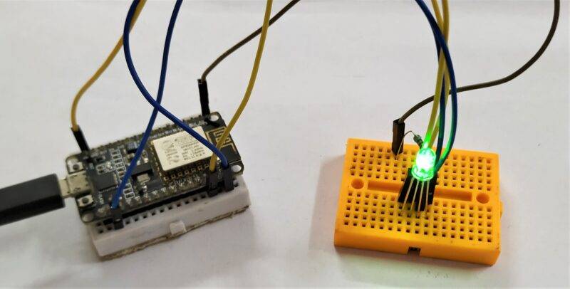
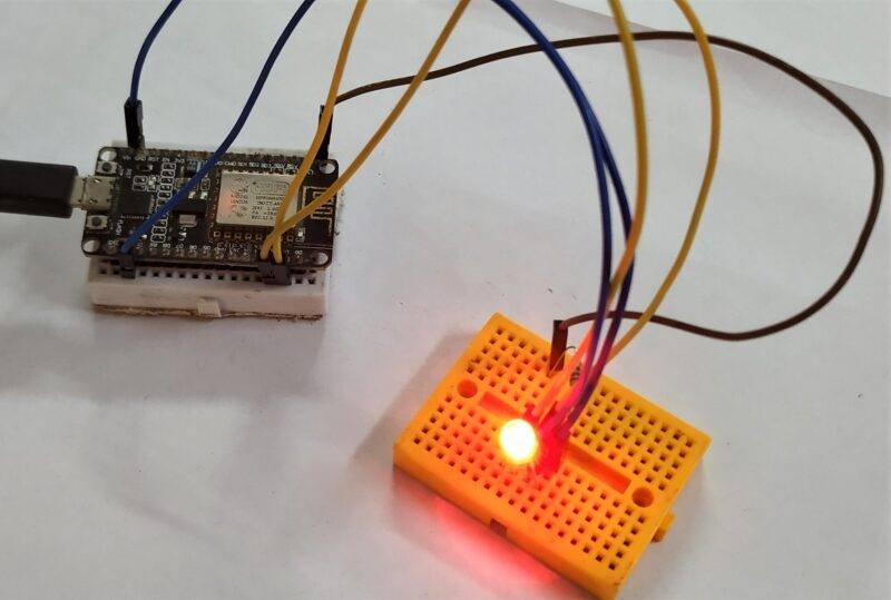
You can use a breadboard for holding the LED upright. After completing the circuit successfully upload the code which is given below.
NOTE: Please upload the code which is given below to the nodemcu as it is. Also, make sure that you have uploaded the correct code as per the circuit that you have made.
Code for Common Anode
 // TECHATRONIC.COM
 // RGB LED COMMON ANODE
 void setup()
 {
   pinMode(16,HIGH);  // Blue led Pin Connected To D0 Pin
   pinMode(5,HIGH);  // Green Led Pin Connected To D1 Pin
   pinMode(4,HIGH);  // Red Led Connected To D2 Pin
 }
 void loop()
 {
    // BLUE LED ON
    digitalWrite(16,LOW);
    digitalWrite(5,HIGH);
    digitalWrite(4,HIGH);
    delay(1000);
    // GREEN LED ON
    digitalWrite(16,HIGH);
    digitalWrite(5,LOW);
    digitalWrite(4,HIGH);
    delay(1000);
    // RED LED ON
    digitalWrite(16,HIGH);
    digitalWrite(5,HIGH);
    digitalWrite(4,LOW);
    delay(1000);
 }
Code for common Cathode
 // TECHATRONIC.COM
 // RGB LED COMMON CATHODE
 void setup()
 {
   pinMode(16,HIGH);  // Blue led Pin Connected To D0 Pin
   pinMode(5,HIGH);  // Green Led Pin Connected To D1 Pin
   pinMode(4,HIGH);  // Red Led Connected To D2 Pin
 }
 void loop()
 {
    // BLUE LED ON
    digitalWrite(16,HIGH);
    digitalWrite(5,LOW);
    digitalWrite(4,LOW);
    delay(1000);
    // GREEN LED ON
    digitalWrite(16,LOW);
    digitalWrite(5,HIGH);
    digitalWrite(4,LOW);
    delay(1000);
    // RED LED ON
    digitalWrite(16,LOW);
    digitalWrite(5,LOW);
    digitalWrite(4,HIGH);
    delay(1000);
 }
hope that you liked this project and if so then please try to make it on your own.
If you are facing any difficulties while making it then feel free to use the comments section given below.
Also, do check out more tutorials on Arduino and Raspberry Pi.
Thanks for reading.