
Table of Contents
Introduction
Hey geeks, hope you are doing fine. Do you know how a 555 timer ic will work in astable mode?
well if not then don’t worry we are here for you. In this article, we are going to make an Astable Multivibrator using 555 timer ic.
Both the states in the astable mode are unstable so the output continuously changes between these two states. Mostly 555 timer ic in the astable mode are used in the making of the oscillators (relaxation oscillators).
We will see the transition in the output due to the charging and discharging of the capacitor.
555 timer is a most usable ic which can be used in any circuit. here we are using this astable multivibrator using 555 timer to generate the square wave.

What is an Astable multivibrator using 555 timer
As we are talking about the astable multivibrator using 555 timer it is not stable and it repeatedly switches from one state to the other. as we see at the monostable multivibrator there we have one state that is stable and another that is not stable.
only you have to trigger a clock to enter the astable mode. when you will switch it by the clock it will return after some time in the stable mode. and there are both states that are stable in bistable.
so, the astable multivibrator using 555 timer does not stable in any of the stages in astable multivibrator using 555 timer . it will continuously change. for example, if there are two-state 0 and 1 in digital electronics it will be from 0 to 1 then 1 to 0 continuously.
Working of astable multivibrator using 555 timer
- Let’s talk about the internal structure of the 555 timer ic, so there are two comparators and a flip flop inside it which are responsible for generating the output.
- The comparators generate the logic signals as per the voltage of the charging and discharging of the capacitor and the supply voltage. At the output, we are receiving a square wave.
- The duty cycle of the square wave will depend on the resistors used in the circuit.
- We have connected an LED at the output pins of the 555 timer ic. Connect a 5 volts dc supply to the negative and positive rails of the breadboard.
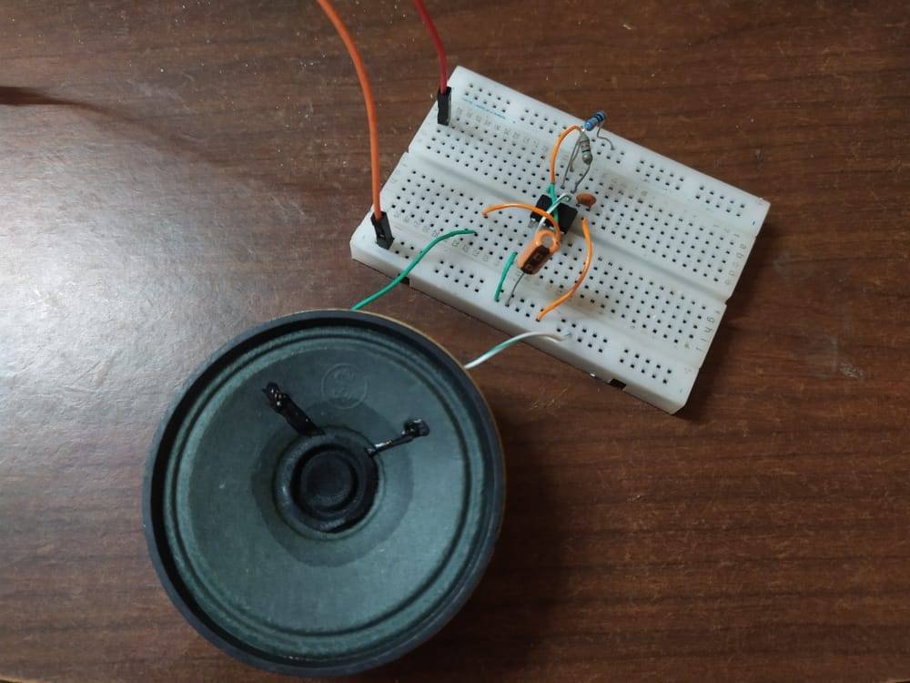
- You can connect an LED, a speaker, or a CRO at the output pins. We are using an LED in this project.
You can also check out the electronic mosquito killer using 555 ic made by us.
Astable multivibrator using 555 timer Components Required

| 555 timer ic | |
| Connecting wires | BUY LINK |
| breadboard | BUY LINK |
| Resistor 1k,100kohm | BUY LINK |
| LED | BUY LINK |
| Capacitors 10 nF and 1 uF |
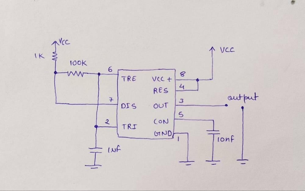
astable multivibrator using 555 timer Circuit Diagram
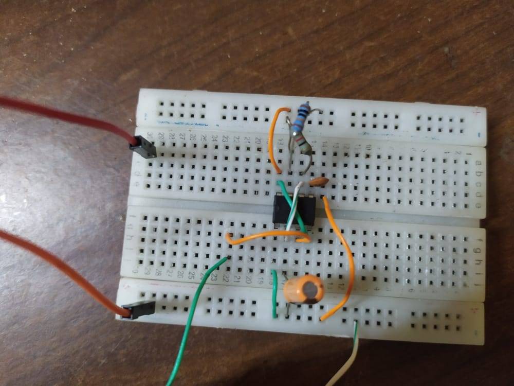
Take a 555 timer ic and place it on the breadboard.
- Identify the pin numbers by finding the notch on the top of the ic.
- Then connect pin 1 of the ic to the negative rail of the breadboard.
- Join pin 8 of the ic to the positive rail of the ic.
- Attach a wire between pins 4 and 8.
- Take a 10 nF capacitor and connect its positive leg with the pin 5 of the ic and negative leg with the negative rail of the breadboard.
- Join pins 2 and 6 together. Connect a 1 uF capacitor with its positive leg to pin number 2 and the negative leg to the negative rail.
- Attach a 1K ohm resistor between pin 7 of the ic and the positive rail.
- Join pins 6 and 7 via a 100K ohm resistor. Use pin number 3 and the negative rail of the breadboard as the output pins.
- Now your circuit is ready for testing. You will get a square wave output at the output pins.
Let’s test the Astable multivibrator using 555 timer ic Circuit

We hope that you understand the working of the astable multivibrator using 555 timer ic.
So, in this astable multivibrator using 555 timer, you can see it will automatically generate the square wave. because it continuously changes its state. so, if we talk in terms of voltage there will be two state one is 5v or the other is 0 volt. so both states will change automatically one by one. 5-0-5-0-5-0 so you will get a square wave in terms of result.
So if you have any queries related to this project then feel free to ask them in the comments section given below. Also, do check out more tutorials on Arduino and Raspberry Pi written by us.
Latest 555 timer Projects.
Fastest Finger First Circuit Using 555 timer IC
555 delay timer with ON/OFF | 555 timer delay off circuit
Mosquito repellent Using 555 Timer | 555 timer projects
Current Detector 555 timer project | current detector 555 circuit
Cell Phone Signal Jammer Using 555 IC | 555 timer project signal jammer