Table of Contents
Introduction
Hey guys, welcome back to Techatronic. Hope you are doing fine. So today we will discuss the working of an esp8266 motion sensor. Well, I hope you know what a PIR sensor is.
If not then don’t worry we will give you a brief introduction to it. Before starting I would like to give you a superb offer that our E-book on Arduino is now available at a special discount. This E-book has 10+ interesting projects with well-explained code and working.
So PIR stands for passive infrared and it is used for detecting the motion of the body in its range. They are available in different ranges and sizes.
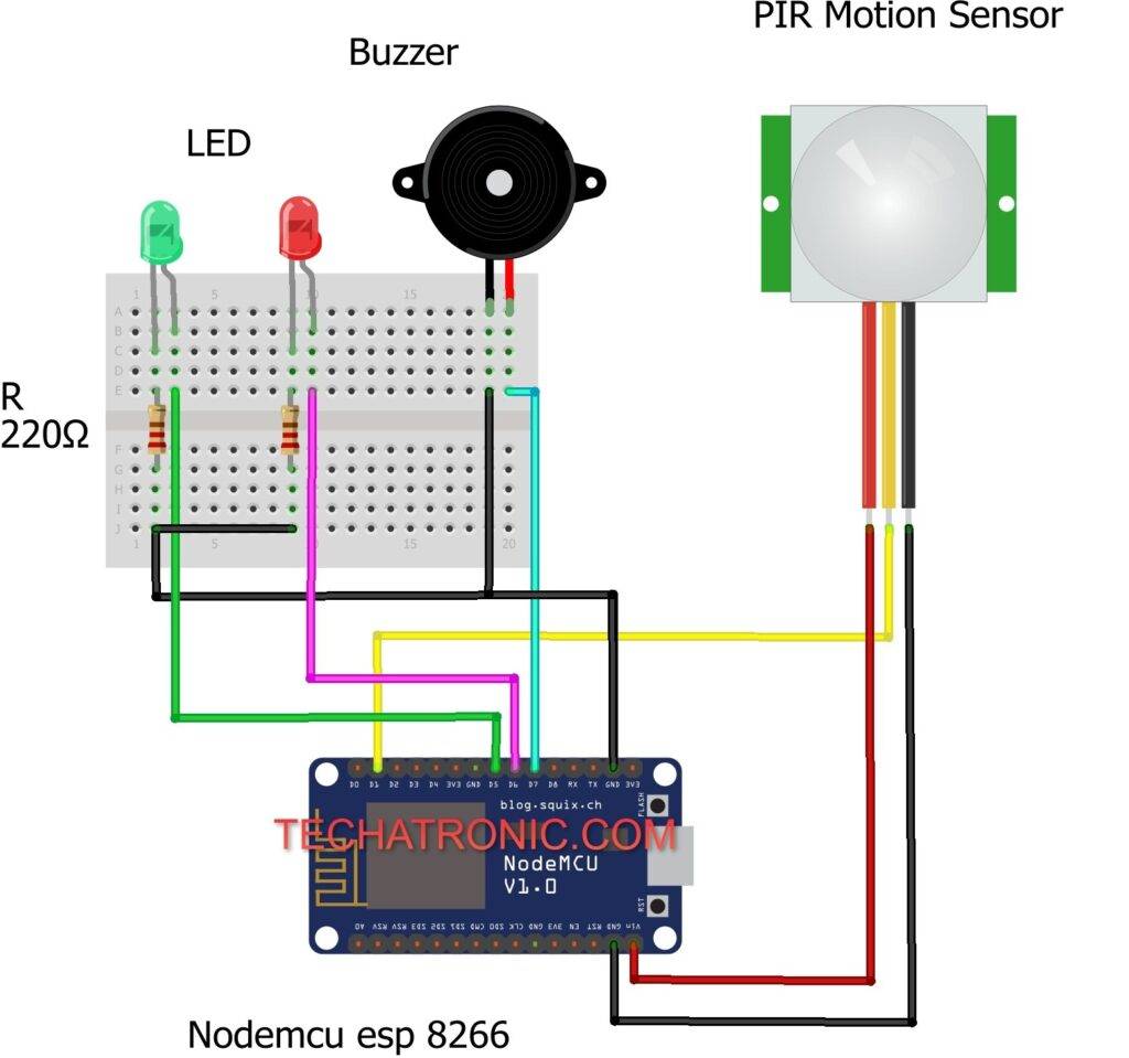
The PIR sensor that we use in this project is of small size and range. Make the connections as per the diagram given below and then upload the code.

esp8266 motion sensor Working
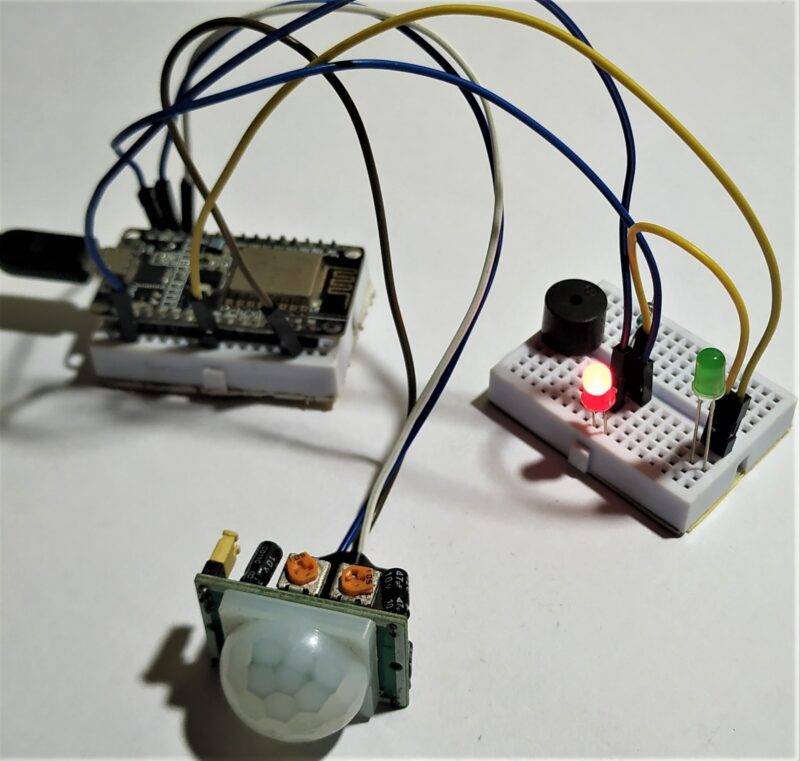
Initially, both the LEDs are turned on and later they will glow according to the signals that are generated by the PIR sensor.
If the PIR sensor detects some movement in its range then both the LEDs will glow and the buzzer also starts beeping else only one LED will glow and the buzzer is silent.
In this esp8266 tutorial,
we will make a useful system. This system is very useful for making various security systems and alert systems. You can also add more components to the circuit to enhance security.
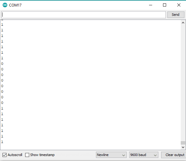
You can also see the values generated by the PIR sensor on the serial monitor screen. We have attached some screenshots below. You can also read the Arduino-based home security system using Arduino made by us.

Simulation on Serial monitor


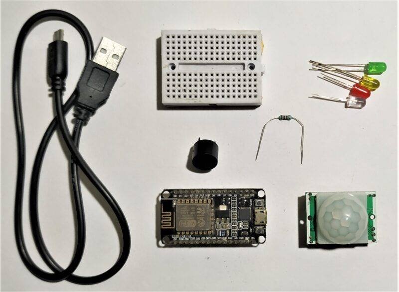
Components Required
| ESP8266 nodemcu | BUY LINK |
| PIR motion sensor | BUY LINK |
| Buzzer | BUY LINK |
| 2.LEDs | BUY LINK |
| Breadboard | BUY LINK |
| Jumper wires | BUY LINK |
| 220-ohm resistor | BUY LINK |
| USB cable for uploading the code | BUY LINK |

esp8266 motion sensor Circuit Diagram

Connection diagram
| Nodemcu esp8266 | PIR Motion Sensor | ||
| Vin, VV | VCC | ||
| GND | GND | ||
| D2 Pin | OUT Pin | ||
| Nodemcu esp8266 | Buzzer | ||
| D7 Pin | Positive | ||
| GND | Negative | ||
| Arduino | LED G | LED R | 220 Ohm Resistor |
| D7 Pin | Anode Pin | ||
| D6 Pin | Anode Pin | ||
| Cathode Pin | Cathode Pin | Terminal 1 | |
| GND | Terminal 2 |
- Connect three jumper wires to the PIR motion sensor.
- Join the VCC pin of the PIR sensor with the VIN pin of the nodemcu.
- Attach the GND pin of the PIR sensor to the GND pin of the nodemcu.
- Connect the OUT pin of the PIR sensor with the digital-1 pin of the nodemcu.
- Take the buzzer and join its positive leg with the digital-7 pin of the nodemcu.
- Attach the negative leg of the buzzer with the GND pin of the nodemcu.
- esp8266 motion sensor interfacing is quite easy.
- After it takes two LEDs and places them on the breadboard.
- Connect the positive leg of the first LED with the digital-5 pin of the nodemcu and the positive leg of the second LED with the digital-6 pin of the nodemcu.
- Join the negative legs of both the LEDs with the GND pin of the nodemcu via 220-ohm resistors.
- Now proceed forward to the code section.
esp8266 motion sensor Code
NOTE: Please upload the code which is given below to the nodemcu.
 // TECHATRONIC.COM
 int val = 0 ;
 void setup()
 {
   Serial.begin(9600); // sensor buart rate
   pinMode(14,HIGH);  // Green led Pin Connected To D5 Pin
   pinMode(13,HIGH);  // Buzzer Pin Connected To D7 Pin
   pinMode(12,HIGH);  // Red Led Connected To D6 Pin
 }
 void loop()
 {
  val = digitalRead(5); // PIR Sensor output pin connected to D1
  Serial.println(val);  // see the value in serial m0nitor in Arduino IDE
  delay(200);      // for timer
  if(val == 1 )
  {
   digitalWrite(14,HIGH); // Green LED ON
   digitalWrite(13,HIGH); // Buzzer ON
   digitalWrite(12,LOW);  // Red LED ON
  }
  else
  {
   digitalWrite(14,LOW);  // Green LED OFF
   digitalWrite(13,LOW);  // Buzzer OFF
   digitalWrite(12,HIGH); // Red LED ON
  }
  }

We hope that you like this esp8266 tutorial and understand the complete procedure that we are trying to explain here. For any doubts regarding this project please ping us in the comments section given below. Also, do check out more such amazing tutorials on Arduino and Raspberry Pi.
HAPPY LEARNING!
