
Table of Contents
Introduction
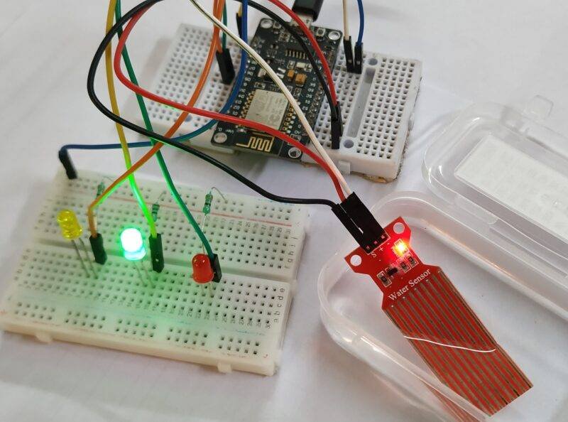
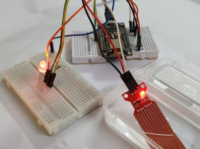
Hi techies, hope you are doing fine. In this article, we are going to discuss the working of an RGB LED module and water level senor with the nodemcu.
Well, what if we combine these two modules in a single project? So keeping this in mind we made a water level indicator system using these two sensors and ESP8266 nodemcu board.
If you don’t have an RGB LED module then it’s okay as we can also use individual red green and blue LEDs instead of it. in this nodemcu tutorial, You can also check out more such interesting projects on Arduino and IoT.
The code and circuit for this project are also provided below for your convenience. Let’s start making it.
Working of the Project
We are sharing two circuits, you can make any one of them and then upload the code. Both the circuits do the same work in this nodemcu tutorial.
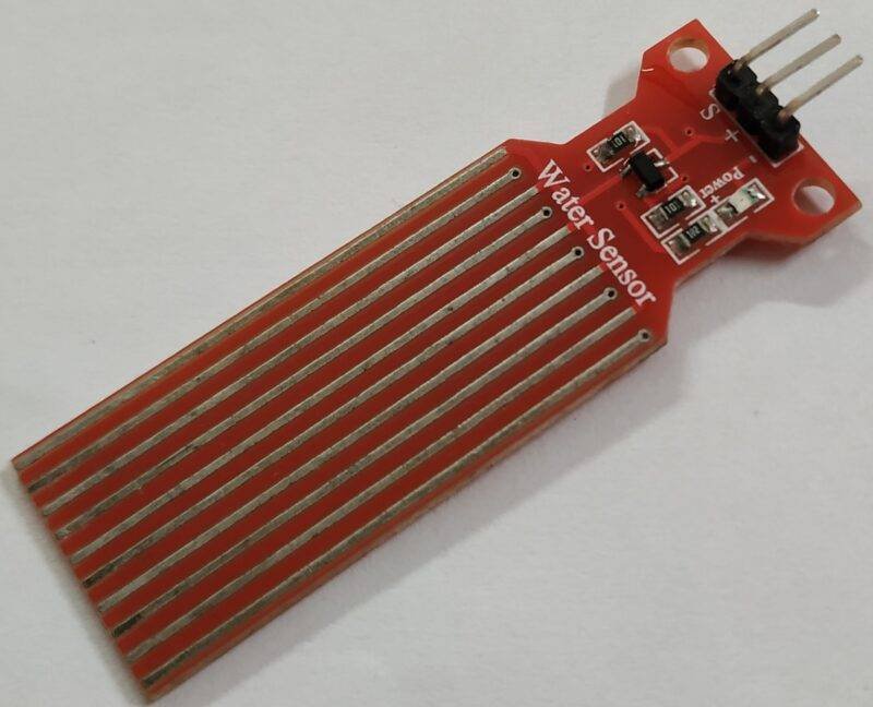
- The water level sensor that we use here generates an output on the basis of the amount of water that is present in the container.
- You have to put it inside the container vertically so that the values are accurate.
- If the water level is low then only the red LED will glow,
- if the water level is moderate then both green and red LEDs will glow,
- and if the water level is full then all three LEDs will glow.
- We give these predefined conditions to the nodemcu.
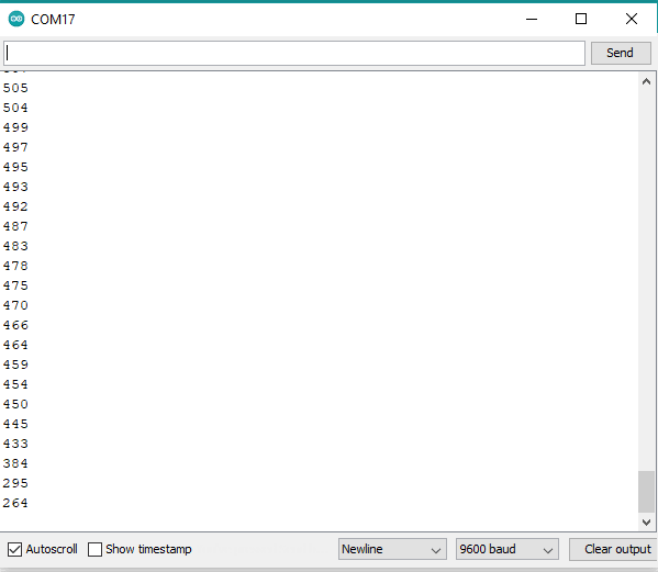
You can also see the values generated by the water level sensor on the serial monitor screen.
Working Simulation

Components Required
- ESP8266 nodemcu board
- KY-016 RGB LED module
- Water level sensor
- Red, green, and blue LEDs
- 220-ohm resistors
- Jumper wires and a breadboard
- USB cable for uploading the code

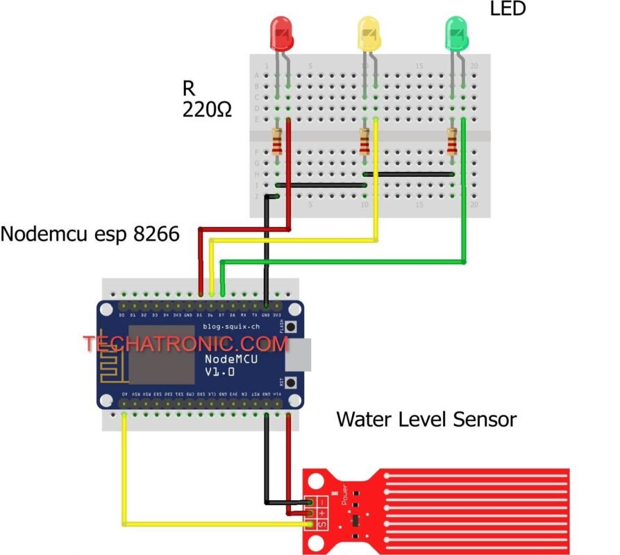
Circuit Diagram for the Project
- Connections for the RGB module

Connection Table
| Nodemcu esp8266 | Water level Sensor |
| VV, Vin | VCC |
| G, GND | GND |
| D1 Pin | S Pin |
| Nodemcu esp8266 | RGB Led Module |
| G , GND | ( – ) |
| D7 Pin | R Pin |
| D6 Pin | G Pin |
| D5 Pin | B Pin |
- Connect the VCC and GND pins of the sensor with the VIN and GND pins of the nodemcu.
- Join the signal pin of the sensor with the analog-0 pin of the nodemcu.
- Now take an RGB LED module and connect its GND pin with the GND pin of the nodemcu.
- Connect the R, G, and B pins of the module with the digital-7, digital-6, and digital-5 pins of the nodemcu.

Connection Table
| Nodemcu esp8266 | Water level Sensor | |||
| VV, Vin ( +5V ) | VCC ( Positive + ) | |||
| G, GND ( Ground ) | GND ( Ground – ) | |||
| D1 Pin | ( S ) OUT Pin | |||
| Nodemcu | LED G | LED Y | LED R | 220 Ohm Resistor |
| D7 Pin | Anode Pin | |||
| D6 Pin | Anode Pin | |||
| D5 Pin | Anode Pin | |||
| Cathode Pin | Cathode Pin | Cathode Pin | Terminal 1 | |
| G, GND | Terminal 2 |
All the connections remain the same but instead of a module connect the positive legs of red, green, and yellow LED with the digital pins of the nodemcu.
Join the negative legs of all three LEDs with the GND pin of the nodemcu via 220-ohm resistors.
Code for the Project
NOTE: Please upload the code which is given below and make sure that you had uploaded the code according to the circuit that you have made.
If you are using an RGB LED module for making this project then upload code A else please upload code B.
- Code A
 // TECHATRONIC.COM
 int val = 0 ;
 void setup()
 {
   Serial.begin(9600); // sensor buart rate
   pinMode(14,HIGH);  // Blue led Pin Connected To D5 Pin
   pinMode(13,HIGH);  // Red Led Pin Connected To D7 Pin
   pinMode(12,HIGH);  // Green Led Connected To D6 Pin
 }
 void loop()
 {
  int s1=analogRead(A0); // Water Level Sensor output pin connected A0
  Serial.println(s1);  // See the Value In Serial Monitor
  delay(100);      // for timer
  if(s1>400 && s1<500 )
   {
    digitalWrite(14,HIGH);   // Blue led ON
   }
  else
   {
   digitalWrite(14,LOW);    // Blue led OFF
   }
  if(s1>500 && s1<550 )
   {
   digitalWrite(12,HIGH);   // Green led ON
   }
   else
   {
   digitalWrite(12,LOW);   // Green led OFF
   }
   if(s1>550 )
   {
   digitalWrite(13,HIGH);  // Red led ON
   }
   else
   {
   digitalWrite(13,LOW);   // Red led OFF
   }
  }
- Code B
 // TECHATRONIC.COM
 int val = 0 ;
 void setup()
 {
   Serial.begin(9600); // sensor buart rate
   pinMode(14,HIGH);  // Red led Pin Connected To D5 Pin
   pinMode(13,HIGH);  // Green Led Pin Connected To D7 Pin
   pinMode(12,HIGH);  // Yellow Led Connected To D6 Pin
 }
 void loop()
 {
  int s1=analogRead(A0); // Water Level Sensor output pin connected A0
  Serial.println(s1);  // See the Value In Serial Monitor
  delay(100);      // for timer
  if(s1> 400 )
   {
    digitalWrite(14,HIGH);   // Red led ON
   }
  else
   {
   digitalWrite(14,LOW);    // Red led OFF
   }
  if(s1>540 )
   {
   digitalWrite(12,HIGH);   // Green led ON
   }
   else
   {
   digitalWrite(12,LOW);   // Green led OFF
   }
   if(s1>580 )
   {
   digitalWrite(13,HIGH);  // Yellow led ON
   }
   else
   {
   digitalWrite(13,LOW);  // Yellow led OFF
   }
  }
Thanks for reading, we hope that you understand that how an RGB LED module and a water level sensor works with a nodemcu board.
If you have any doubts regarding this project then please ask them in the comments section given below. You can also read more articles on Arduino and Raspberry Pi written by us.