

Hey geeks, welcome back to Techatronic. In this article, we are going to learn how to make an Arduino-based Home security system using a PIR motion sensor. The security of the home is one of the major problems that everyone facing at the present time. There are some gadgets available in the market that help a lot to secure your house but some of them are not pocket-friendly and also need maintenance at regular intervals. If you like this project, please check more cool projects based on Arduino. For making this home security system we use an Arduino UNO and a PIR motion sensor. You can check out our Fingerprint door lock system using Arduino. Do you know how a PIR sensor works with Arduino, if not please check it out first? . Complete the circuit and upload the given code to use the security system.
How Does the Security System work?
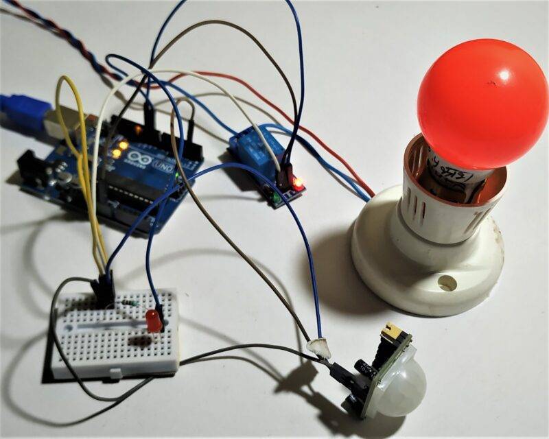
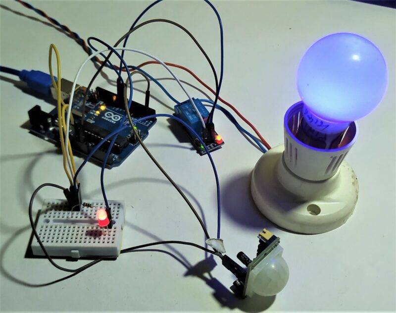
A Passive Infrared Sensor is used to detect the motion of the object that moves in or out of the sensor’s range. It comes with two trim pots for adjusting the sensitivity and the delay time. You can adjust them according to usage. When the sensor detects someone’s movement in its range then HIGH output is generated otherwise LOW output is generated. You can also observe the real-time readings on the Arduino serial monitor as shown below. When the HIGH output is received by Arduino then the LED will turn on and an AC bulb is also turn on. We use a Relay module here for turning the AC bulb on and off. While working with AC load please take necessary precautions.

Components Required
| Arduino UNO | BUY LINK |
| USB cable for the project | BUY LINK |
| PIR motion sensor | BUY LINK |
| Jumper wires | BUY LINK |
| LED and a 220-ohm resistor | BUY LINK |
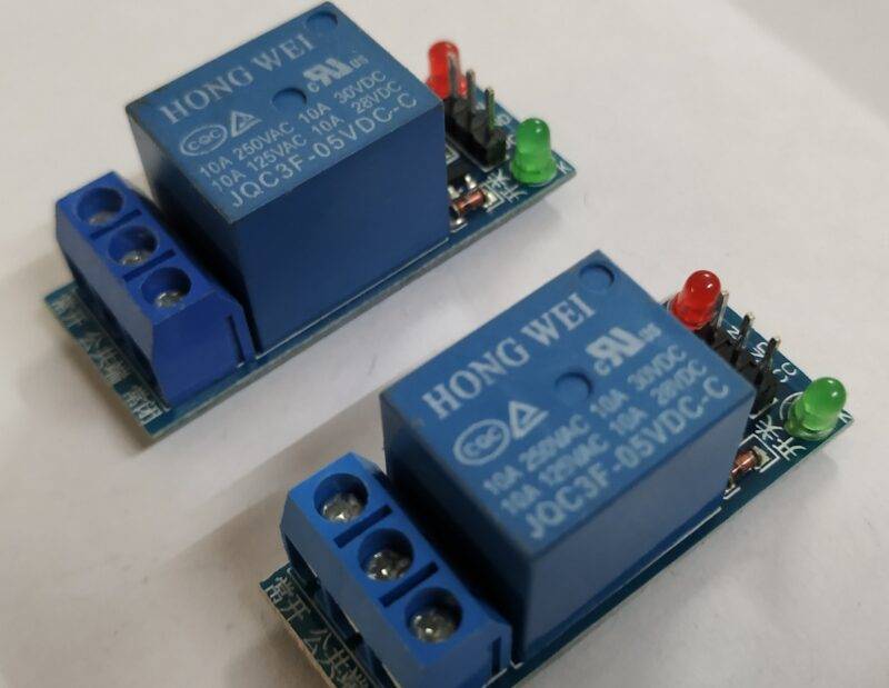
| Relay module | BUY LINK |
| AC power supply | BUY LINK |
| AC bulb | BUY LINK |
| Power supply | BUY LINK |
You can buy all components together-BUY LINK

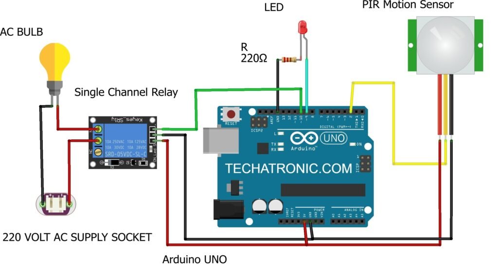
Circuit Diagram for the Project
|
Arduino UNO |
PIR Sensor | |
|
D2 Pin |
OUT Pin | |
|
( +5V ) |
VCC | |
|
GND |
GND | |
|
Arduino UNO |
Relay Module | |
|
D10 Pin |
IN1 OUT Pin | |
|
( +5V ) |
VCC | |
|
GND |
GND | |
|
AC Bulb |
220 V AC Supply |
Relay Module |
|
|
|
Normally Open |
|
|
Phase |
Common |
|
Terminal 1 |
|
Normally Closed |
|
Terminal 2 |
Neutral |
|
|
Arduino UNO |
LED |
220-ohm Resistor |
|
D9 Pin |
Anode Terminal |
|
|
GND |
|
Terminal 1 |
|
|
Cathode Terminal |
Terminal 2 |
You have to make the connections according to the circuit diagram given above. Attach the 5-volt pin of the Arduino with the VCC of the PIR motion sensor and the relay module. Connect the GND pin of the Arduino with the GND of the PIR sensor and the relay module. Join the OUT pin of the PIR sensor with the digital-2 pin of the Arduino. Connect the DATA pin of the relay module with the digital-10 pin of the Arduino. On the other side of the relay module make the connections with the AC load and bulb as shown in the diagram. Connect the positive leg of the LED with the digital-9 pin of the Arduino and the negative leg with the GND of the Arduino through a 220-ohm resistor. You can use a breadboard for making the common connections. Now, upload the code and your security system is ready to use.
Code for the Project
NOTE: Please upload the code which is given below to the Arduino as it is.
 // TECHATRONIC.COM
 int val = 0 ;
 void setup()
 {
 Serial.begin(9600);   // sensor buart rate
 pinMode(2,INPUT);    // pir sensor output pin connected to D2
 pinMode(9,OUTPUT);   // led pin
 pinMode(10,OUTPUT);   // Relay PIN
 digitalWrite(10,HIGH); // Relay Normaly OFF
 }
 void loop()
 {
 val = digitalRead(2); // pir sensor output pin connected
 Serial.println(val); // see the value in serial monitor in Arduino IDE
 delay(100);
 if(val == 1 )
 {
 digitalWrite(9,HIGH);  // LED ON
 digitalWrite(10,LOW);  // Relay ON
 }
 else
 {
 digitalWrite(9,LOW);  // LED OFF
 digitalWrite(10,HIGH); // Relay OFF
 }
 }
After uploading the code open serial monitor


We hope that you can try to make this project on your own. If you are facing any difficulties and errors do inform us in the comments section below. View more Tutorials on Arduino and Raspberry Pi.
HAPPY LEARNING!