
RF Module, this is the simple and very first of the RF modules, beginners used to experiment with. Let’s learn about it.
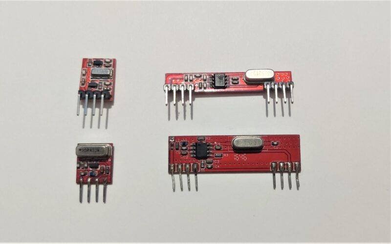
- The version which I’m going to explain today is the 433MHz RF Transmitter and Receiver Module, which comes in red color PCB. This is very cheap and easily available in the market for under 4$.
- The durability is a bit compromised as the PCB is quite thin and can easily be broken off if enough pressure is applied.
- This module has single-pin data communication, so the transfer rate is prefixed. There are many versions and clones of this RF Transmitter and Receiver Module but the working of each is the same.
- The one which I’m going to demonstrate is the 433Mhz ASK module, which is commonly available in all offline and online shops. I’ll also try to cover some other clones I have lying around.
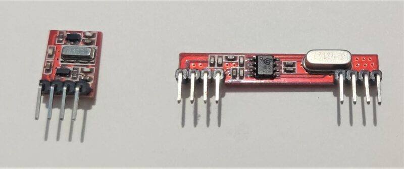
Table of Contents
Construction
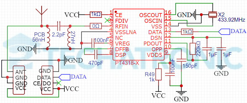
- Above is the schematic of the 433MHz ASK RF Module, both RF Transmitter and RF Receiver. Although both schematics are drawn from the real modules by reverse engineering, the transmitter schematic is not guaranteed accurate as of that of the receiver.
- In Transmitter, the schematic is the very basic one that can be found on the internet. But that of the rf receiver is built-in consideration that of the PT4318-X datasheet.
- According to the datasheet the rf receiver can be used to receive both 433MHz & 315MHz signals but from the PCB, not any hardware is seen though. So it might be some passive SMD components that need to be replaced.
- The range of coverage of signals of the module is said to be 500 m in open ground but in an experiment in a real scenario, it might be less than 20 m. To enhance this, you can use an antenna of length λ/4.

Working
- The working of the module is purely software-based. So here I’ll explain the working of the hardware and for software, part visit projects based on it.
- First, in the transmitter part, the power supply can be connected to a 3 to 12 V supply(for receiver 5V only). When data is received or pushed into the transmitter, it passes through a resistor filter. Further, it is mixed with a 433MHz frequency signal to modulate it. Then it is transmitted through the antenna pin.
- In Receiver, it is different, PT4318 which is a low power single chip OOK/ASK super-heterodyne receiver for the 315 MHz and 434 MHz frequency bands.
- The detail of how this IC works can be understood with a thorough reading of its datasheet. In this configuration, it can support data rates up to 10kb/s.

Advantages
- These sensors are quite cheap for a beginner to start with also they are very easy to use either with microcontrollers or some encoder or decoder IC like HT12D/E.
- This module comes with single-pin Data transmitting and receiving which makes it easier to use as compared to other RF module which uses communication like SPI or I2C.
- Also, the signal can be sent and received using multiple modules or any matching frequency and algorithm module, you just need to keep in mind the transmitting frequency for multiple connections.
Disadvantages
- The transfer range keeps fluctuating with the power input and antenna length, so you have to make sure of both factors.
- Also, the Transfer speed is a bit slow and also varies with range, if not transferring in the open sky or there are some obstacles between transmitter and receiver.
- The module is hard to repair as all the components are SMD and there are many schematics and many versions available which will take ample time to successfully repair, rather you may buy a new pair.
Applications
- As these sensors are not quite popular, there are few articles on this but a tutorial for them has been issued on our website, make sure to read it for more information. Also, other related information and projects are mentioned below.

FAQ
Q. What is the working voltage and the logic level of the RF Transmitter and Receiver module?
The working voltage for the RF module is 3V—6V and the logic level is the same as the input voltage.
Q. Will the range and performance of the sensor will affect if the antenna is not used?
Yes, it will be affected greatly also make sure to use the antenna of the required length for better results.
Related Projects
RF Module Control Using Arduino
Arduino RF Module Automatic Door Using DC Motor
RF transmitter and Receiver with Arduino
Automation Using TSOP 1738 Sensor And Arduino
Weather Monitoring System using Arduino | Weather Station using NRF