Hey guys, welcome back to Techatronic. This is another post in the Arduino tutorial. RF transmitter and receiver with Arduino is very simple and usable it can use in any project. RF 433 MHz modules will be used in this project. a very small but very useful sensor module. our first project by this module was a remote control system for bikes. in that system there were 4 small push buttons at the transmitter and 4 relays at the receiver. one button is associated with the one relay. so there four relays controlled by the remote. so, this can be used at many places another example I have made is curtain-raiser. you can control your curtain-raiser through this system.

What is Rf 433 module?
RF module is a radio frequency module that works on the 433 MHz. and the range of this module is near about 50 -60 meters which is enough to control any device by the wireless remote. rf module with Arduino is more accurate than the single use of this module. if you Want to add wireless capabilities into your next Arduino project, for less than the price of the market? then 433MHz RF Transmitter and Receiver Modules are the best alternatives! They can available online for less than two dollars for a pair, making that system one of the most inexpensive wireless communication options that you can get. these modules are super tiny, allowing you to incorporate a wireless interface into almost any project.
Rf transmitter
DATA pin accepts digital data to be transmitted.
VCC supplies power to the transmitter. This should be any positive DC voltage from 3.5V to 12V.
GND is a ground pin.
The antenna is a pin for an antenna. which should be connected externally and this is very important.
Rf receiver
VCC supplies power for the receiver.
DATA pins for the data pin. The two center pins are internally tied together.
GND is a ground pin.
Antenna is a pin for an antenna. which should be connected externally and this is very important.
Why this rf Module?
there are many wireless communication modules available in the market. such as Bluetooth, esp, and, nrf but this rf module the cheapest and smallest module which can be used also without a controller. it has a good range of more than Bluetooth and wifi. and also it has can connect automatically when getting in the range. you don’t need any password or anything to connect it. so, I think is the simplest and easiest working module. anyone can use this with the Arduino. and we are sharing all the detail about the tutorial.
There is already a library given for the rf module. which you need to download and install in your Arduino ide. then the rf module will work with any code. download library from this link
how to include library?

follow the above-given instruction. Click on the sketch in the left side upper corner. and click on the add zip library.

After adding this library. start your code or copy the given code.
Components required:-
- Arduino Uno
- 433 mf RF module
- breadboard
- jumper wire
- LEDs
- 220-ohm resistor

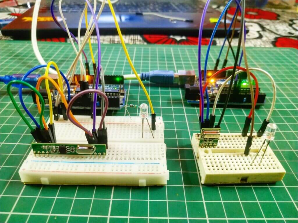
rf module with Arduino circuit diagram

Transmitter Connection Table
| Arduino UNO | RF Transmitter Module | |
| ( +5V ) | VCC | |
| GND | GND | |
| D12 Pin | Data pin | |
| Arduino | LED R | 220 Ohm Resistor |
| D9 Pin | Anode Pin | |
| GND | Terminal 1 | |
| Cathode Pin | Terminal 2 |
Receiver Connection Table
| Arduino UNO | RF Receiver Module | |
| ( +5V ) | VCC | |
| GND | GND | |
| D12 Pin | Data pin | |
| Arduino | LED R | 220 Ohm Resistor |
| D9 Pin | Anode Pin | |
| GND | Terminal 1 | |
| Cathode Pin | Terminal 2 |
Arduino rf module code
Transmitter code
 // Techatronic.com
 #include <VirtualWire.h>
 const int ledPin = 9;
 char *data;
 void setup()
 {
  pinMode(ledPin,OUTPUT);
  vw_set_ptt_inverted(true);
  vw_set_tx_pin(12);
  vw_setup(4000);
 }
 void loop()
 {
  data="0";
  vw_send((uint8_t *)data, strlen(data));
  vw_wait_tx();
  digitalWrite(ledPin,HIGH);
  delay(500);
  data="1";
  vw_send((uint8_t *)data, strlen(data));
  vw_wait_tx();
  digitalWrite(ledPin,LOW);
  delay(500);
 }
Receiver code
 #include <VirtualWire.h>
 void setup()
 {
 vw_set_ptt_inverted(true); // Required for DR3100
 vw_set_rx_pin(12);
 vw_setup(4000); // Bits per sec
 Serial.begin(9600);
 pinMode(9, OUTPUT);
 vw_rx_start(); // Start the receiver PLL running
 }
 void loop()
 {
 uint8_t buf[VW_MAX_MESSAGE_LEN];
 uint8_t buflen = VW_MAX_MESSAGE_LEN;
   Serial.println();
 if (vw_get_message(buf, &buflen)) // Non-blocking
 {
 if(buf[0]=='0')
 {
 digitalWrite(9,HIGH);
 }
 else
 {
 digitalWrite(9,LOW);
 }
 }
 }
Upload the Given code into the Arduino. if you have any problem with the uploading you can ask us or you can visit the webpage which can help you.
Learn 10+ basic activity & sensor interfacing with our Arduino ebook. Well explained program. And brief circuit diagram WhatsApp and email support. which will help you to learn basic electronics, Arduino Coding, Sensor interfacing with Arduino, Arduino, and much more. buy Arduino Ebook to learn https://techatronic.com/arduino-ebook/


